Building logical gates with slime mold
A JOURNEY IN PROGRESS
Before coming to the BioHack Academy I already had heard about Slime Mold and there capability to solve network/traveling salesman problems, like this maze.
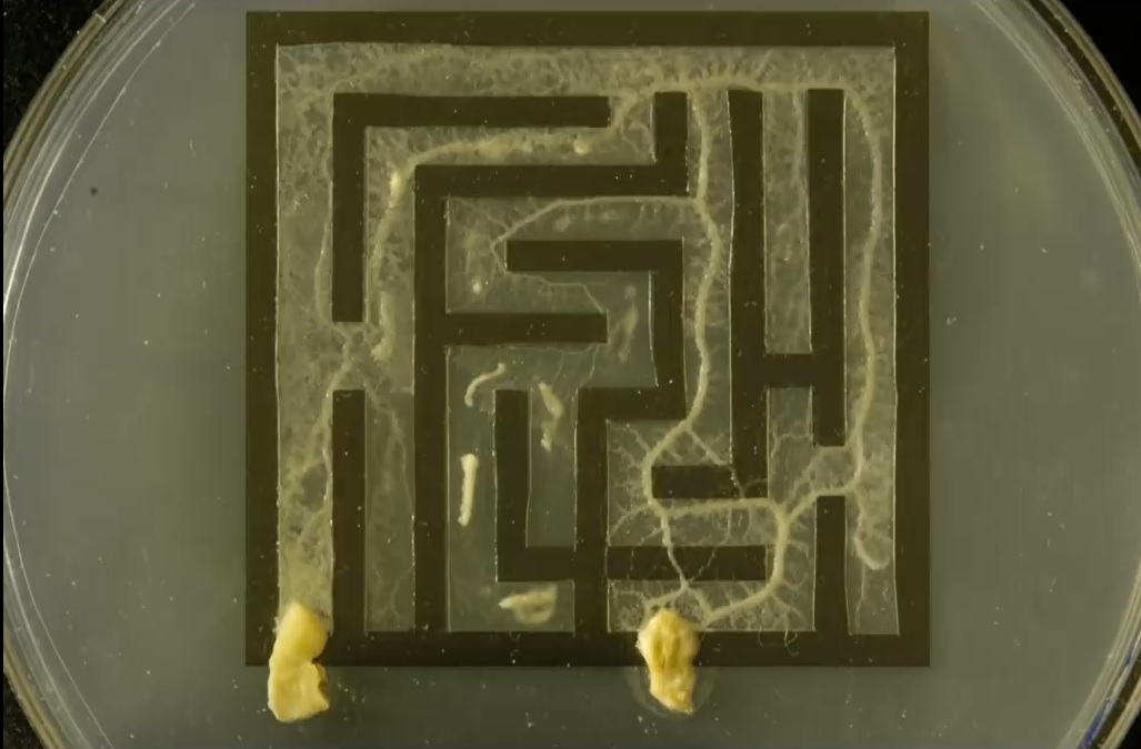
Slime mold solving maze on YouTube
There is even a professional problem solver Slime Mold Andi with its own Twitter page
So I was very pleased to learn that there was slime mold available at the BioHack Academy to use. However repeating something I knew was already possible would not be much interesting. So after some googling,
Discovering Boolean Gates in Slime Mould
Slime mold microfluidic logical gates
Slime mould logical gates: exploring ballistic approach
I discovering that there is a lot of very difficult computation possibilities with smile mold. Which is very cool because this is on the crossroad of biology and computer science. I decide that I would start with the fundamental building blocks, namely try to build Logical Gates and progress from there.
Grow Test
First I needed to get some feel for this strange behaving organism, so I started with some grow tests to see how they behave. They were grown in Petri dishes. By placing them on a starting point (S) with 1 oat meal flake as limited food source and a big food source (F) further on.
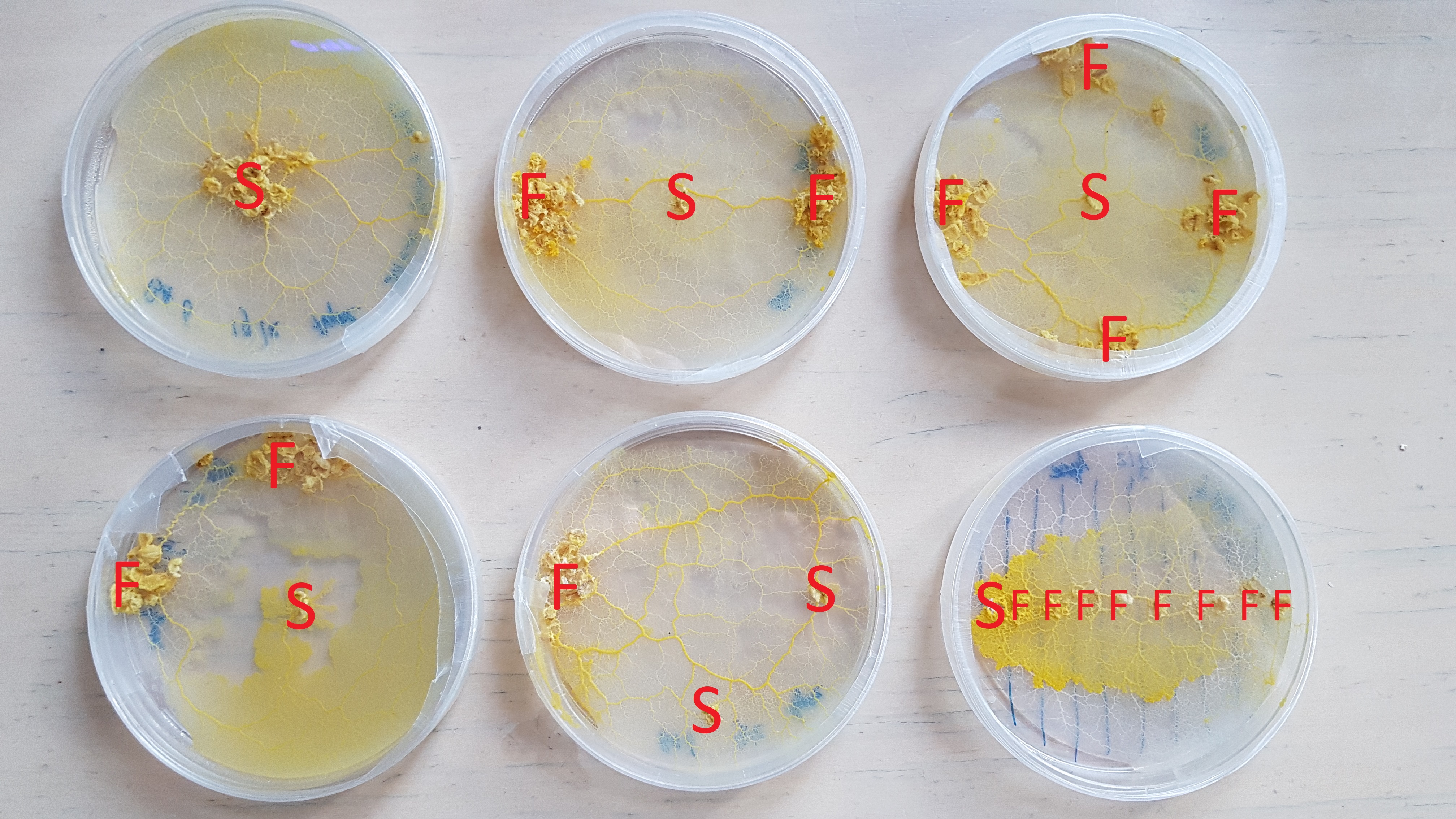
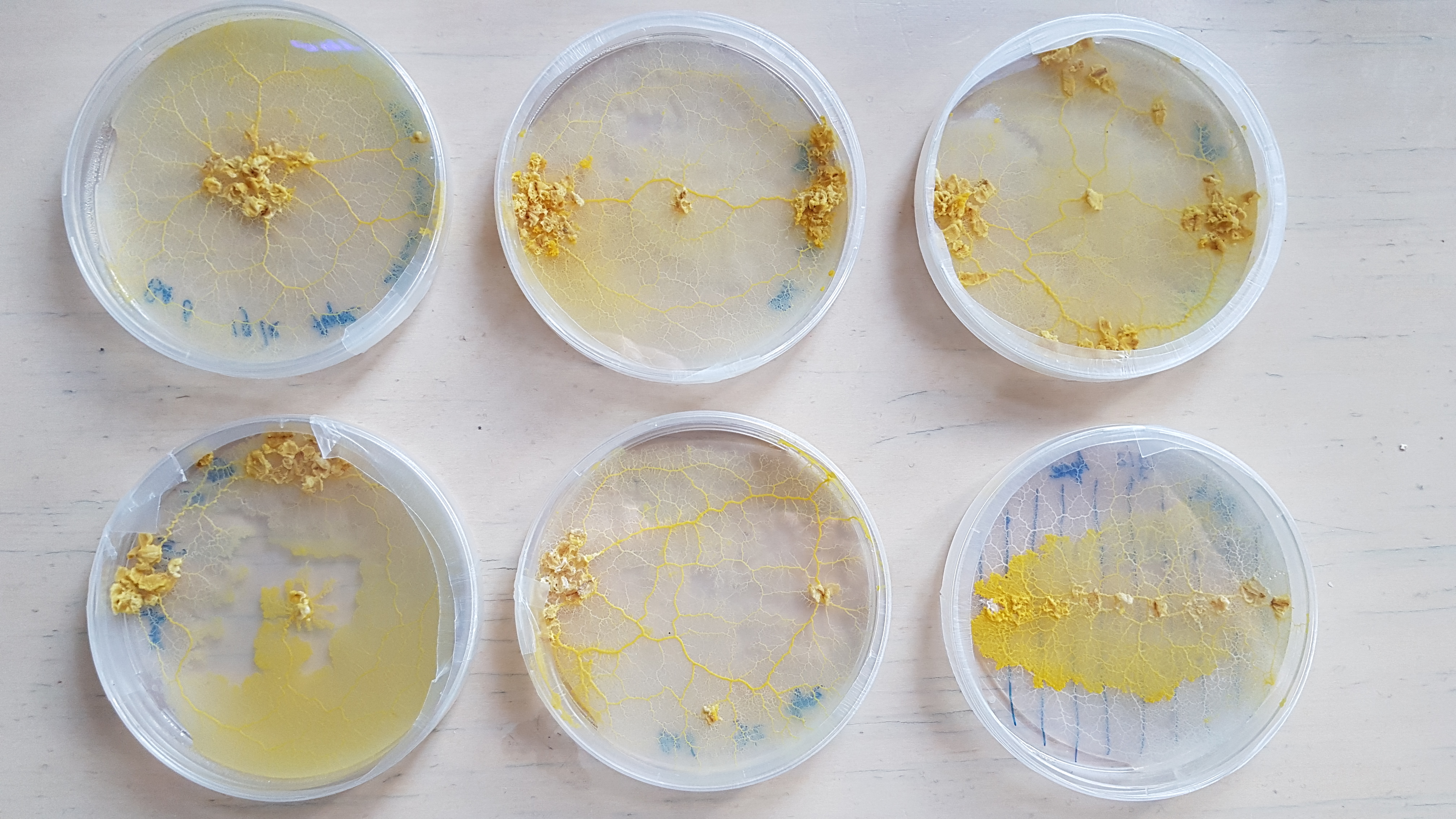
Detail pictures:
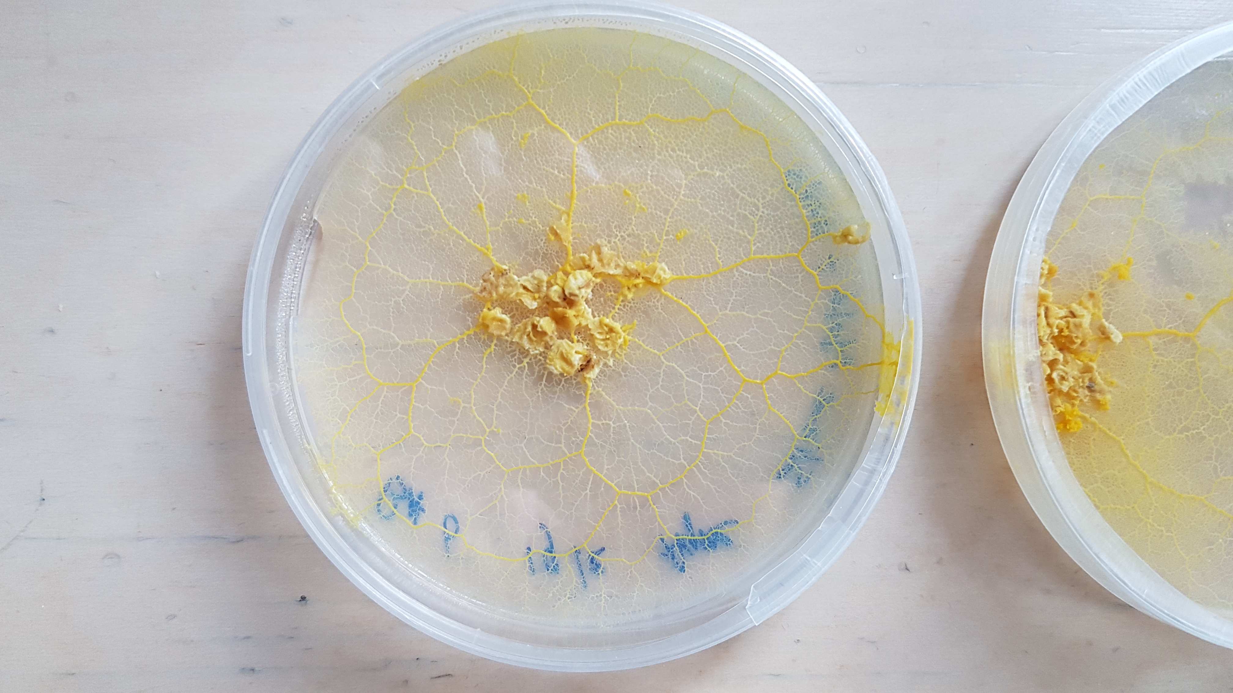
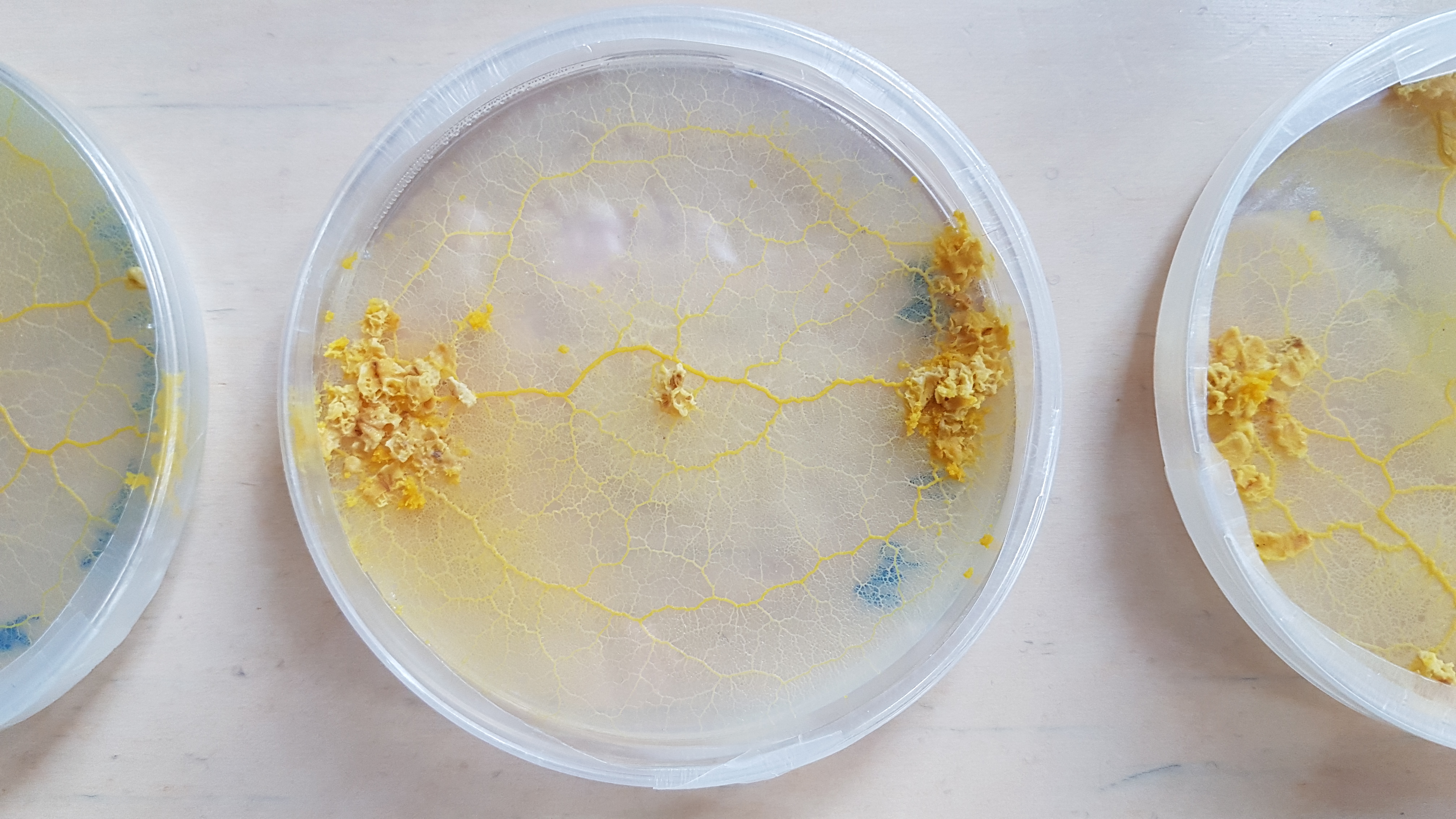
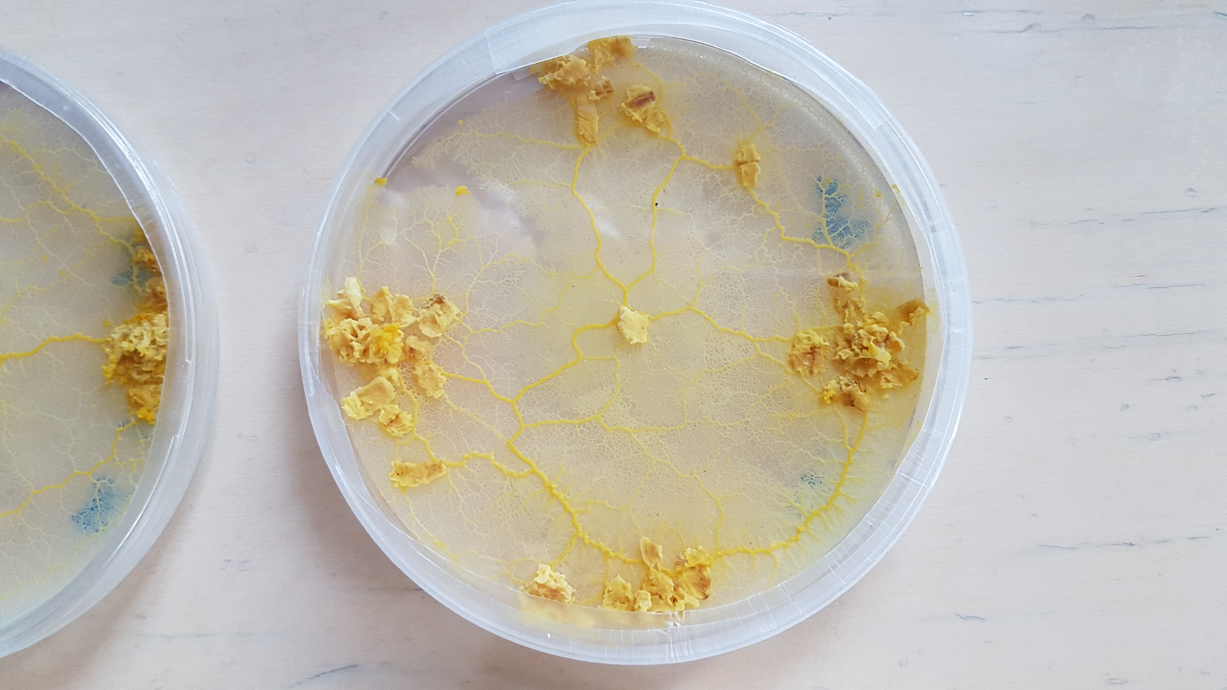
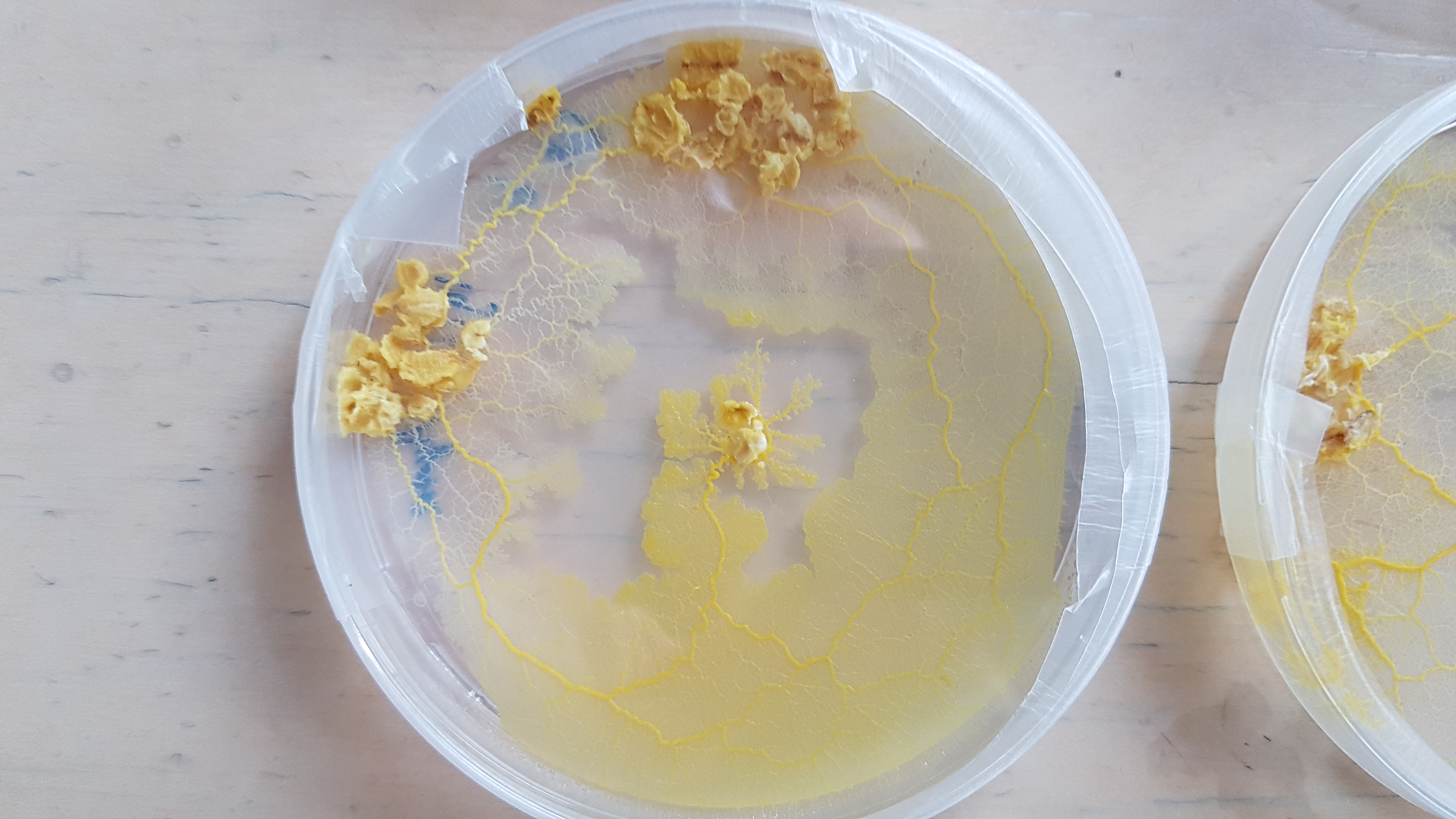
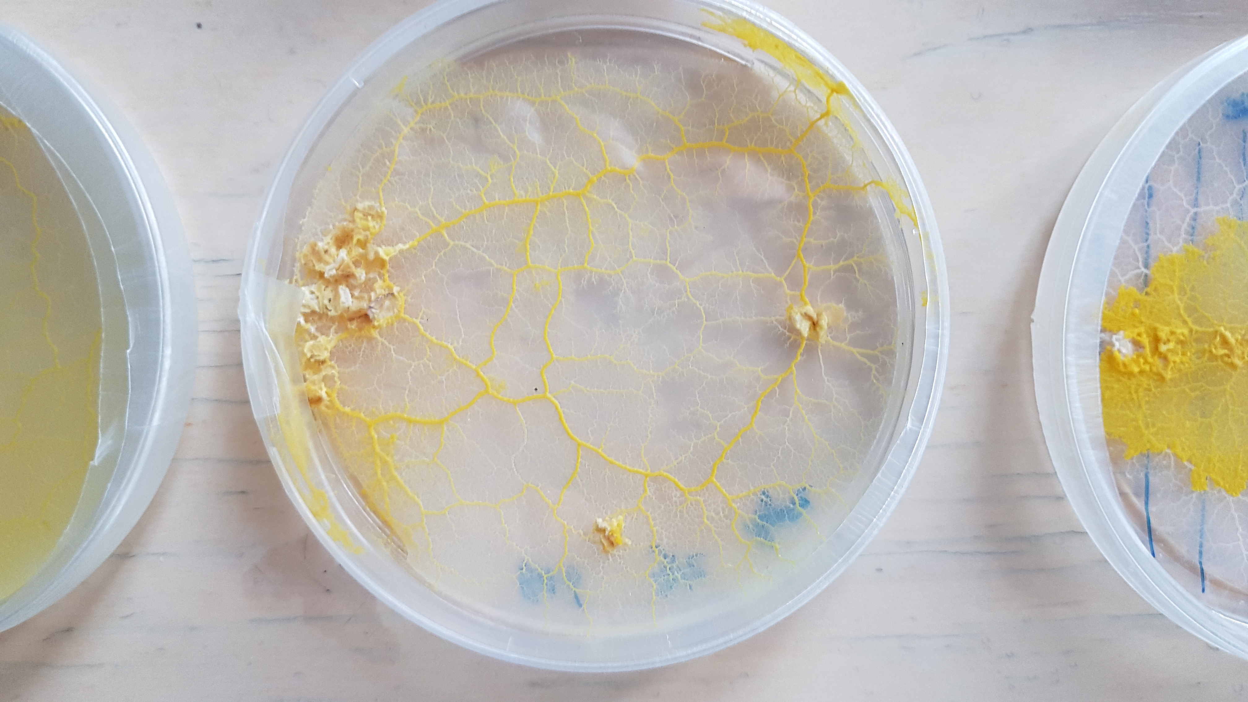
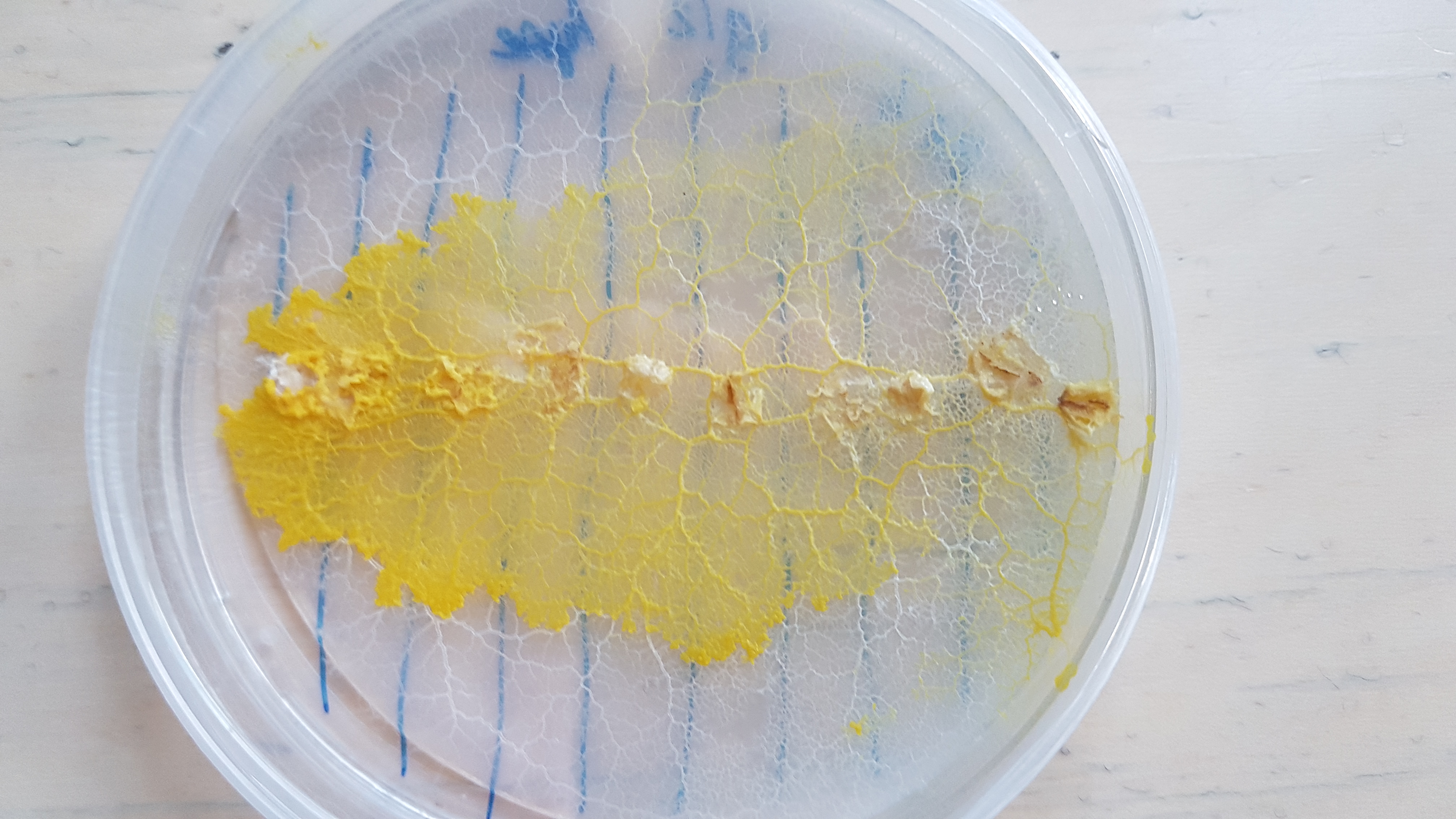
And the grow patterns 1 week later:
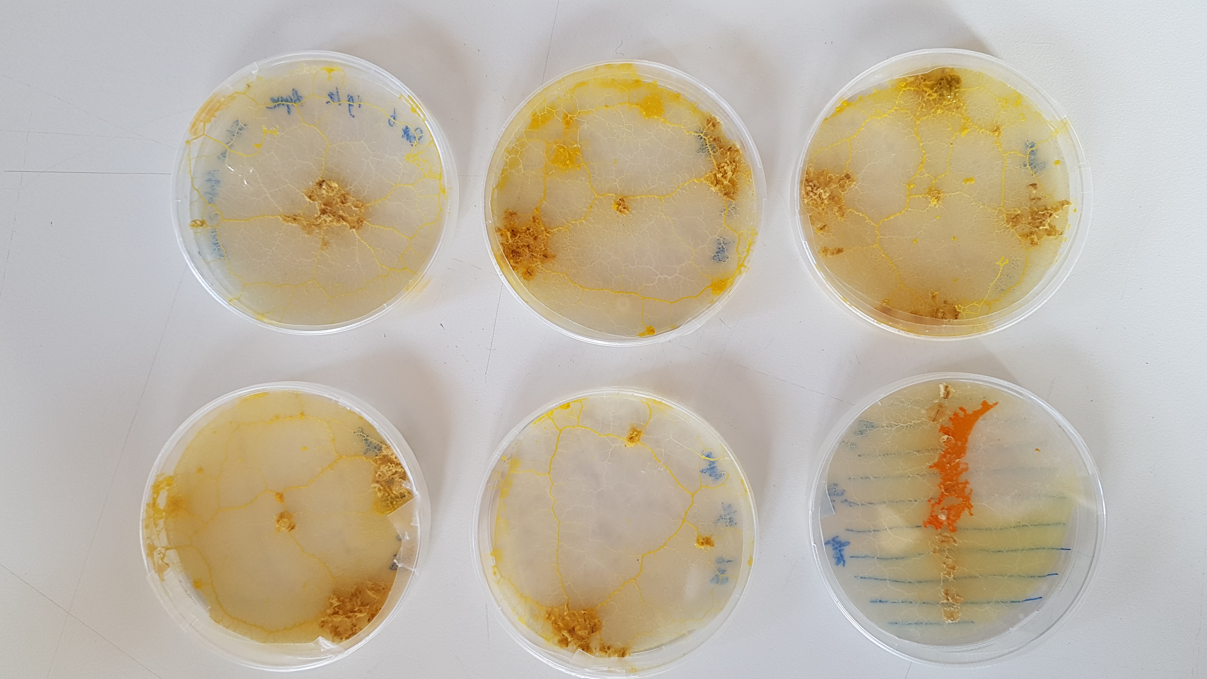
Pictures of the slime mold holding Petri dish showing there incredible capability to grow
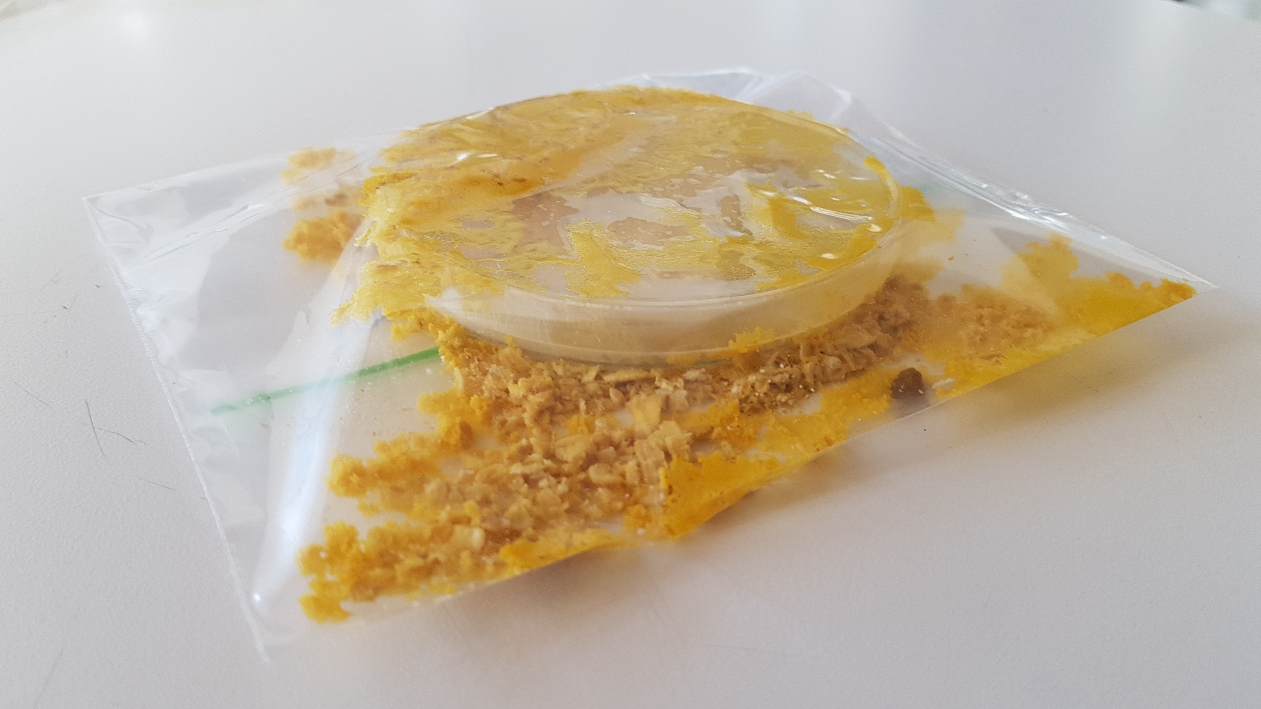
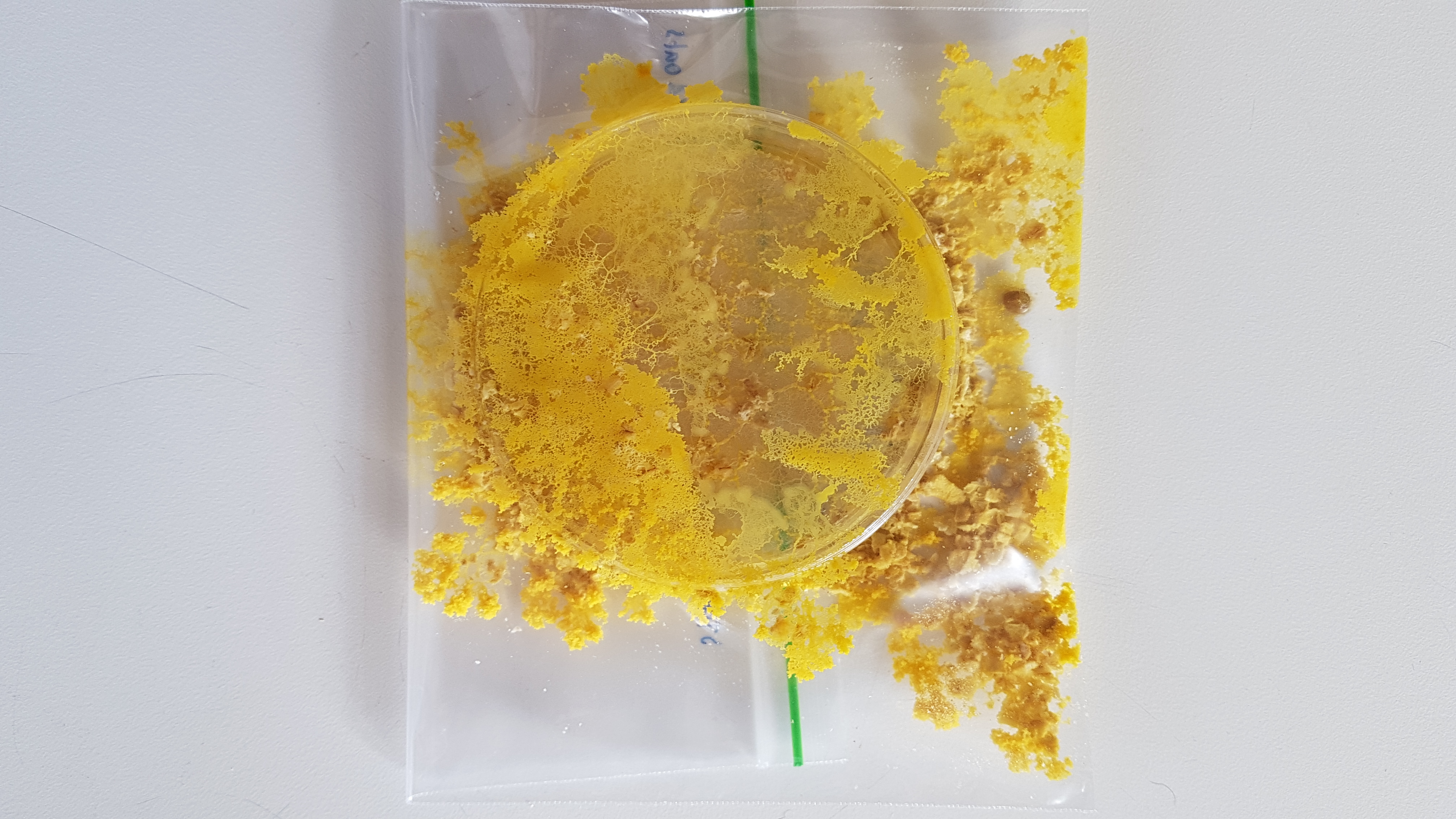
Light inhibition grow test setup
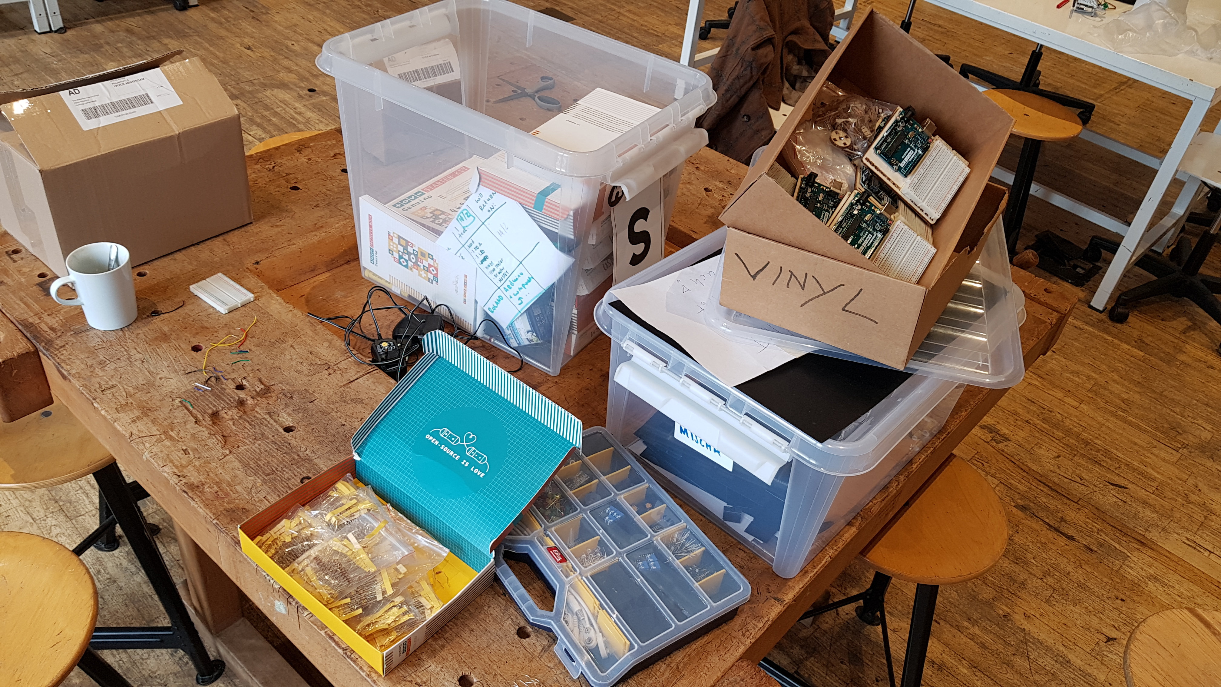
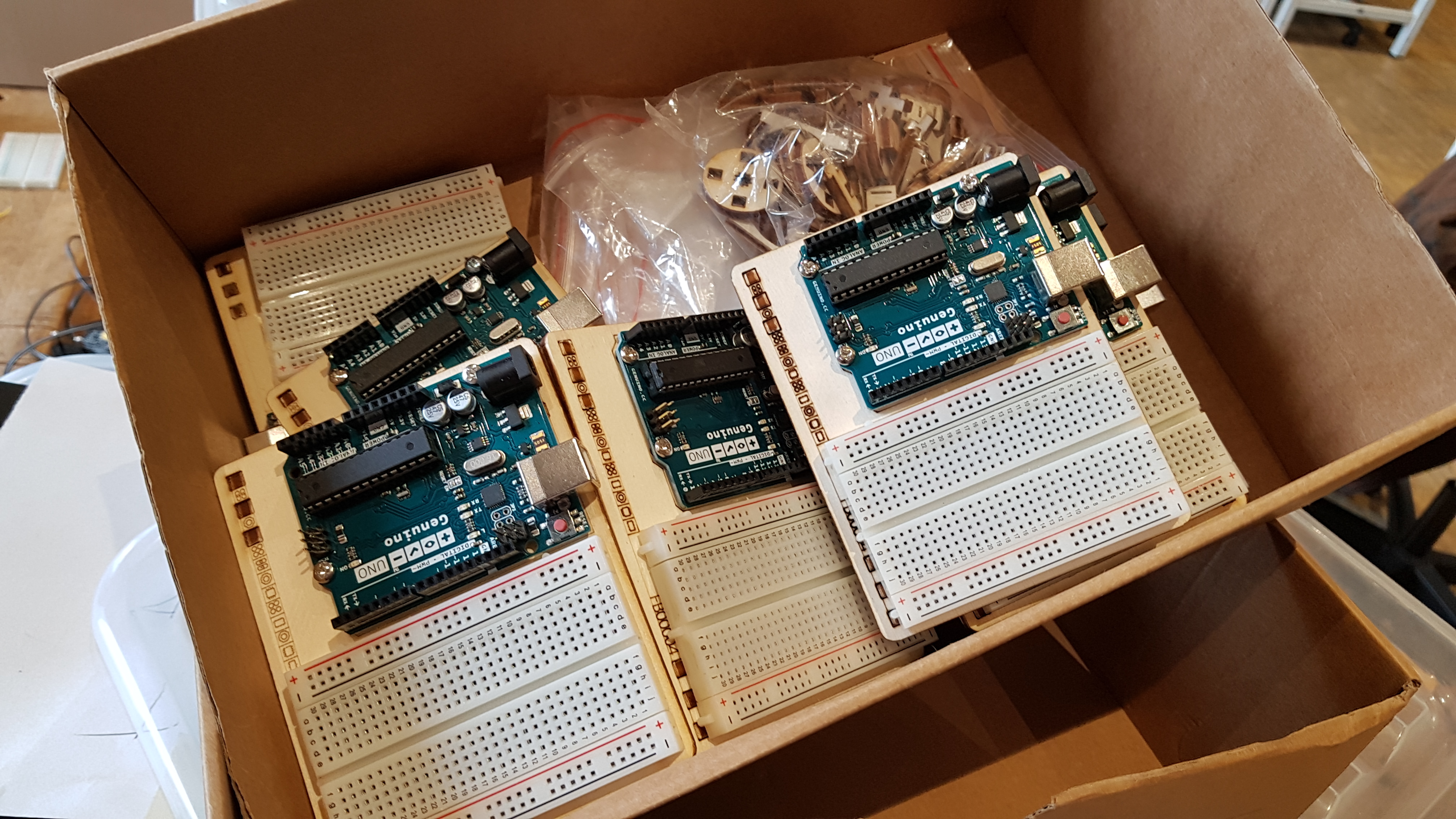
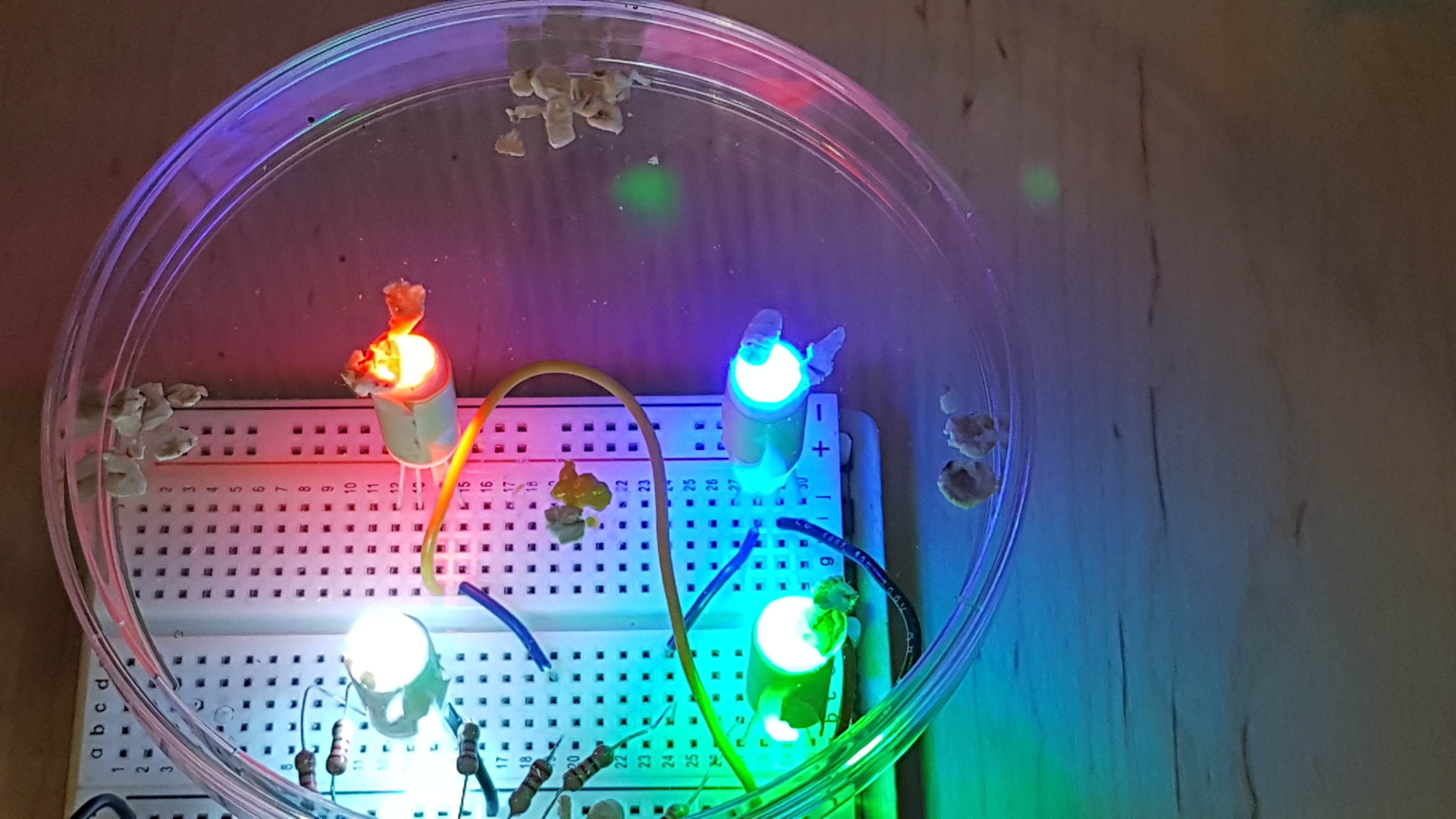
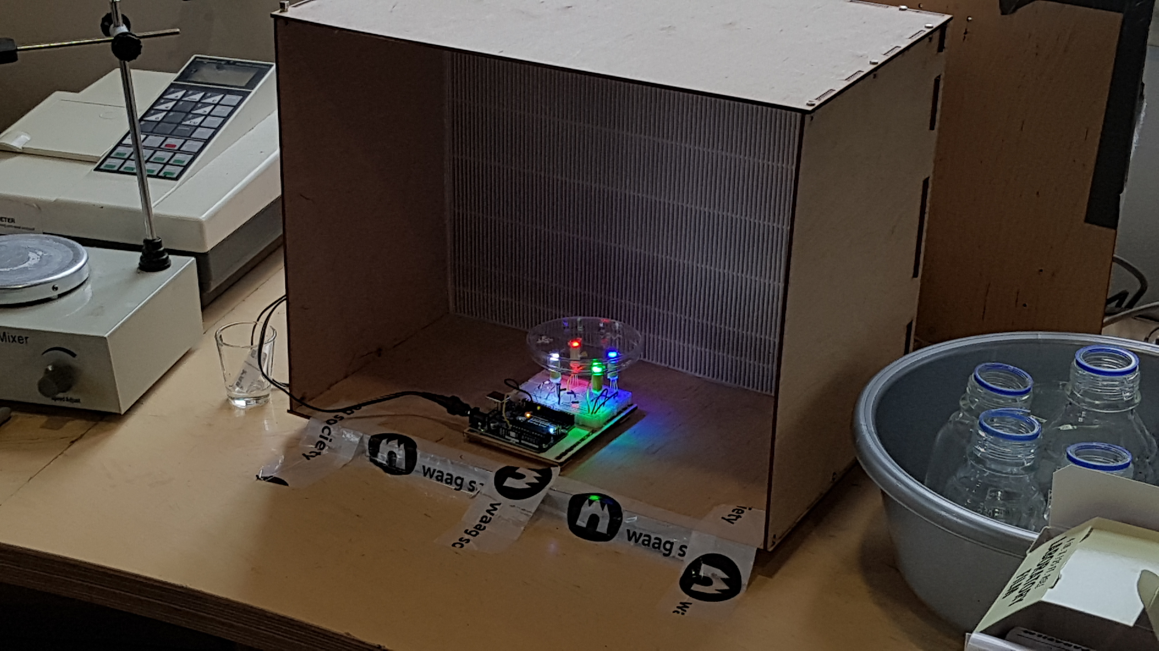
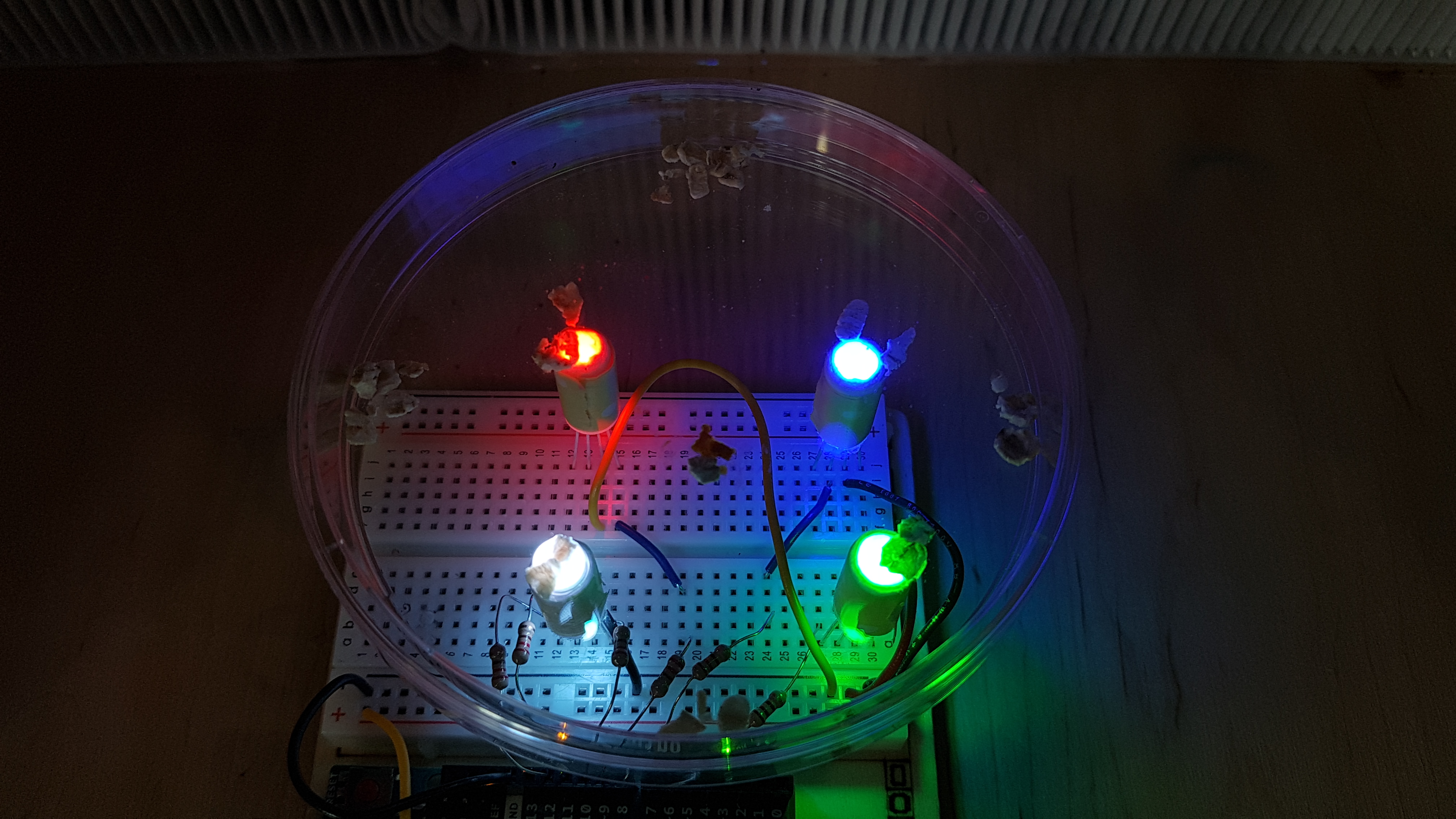
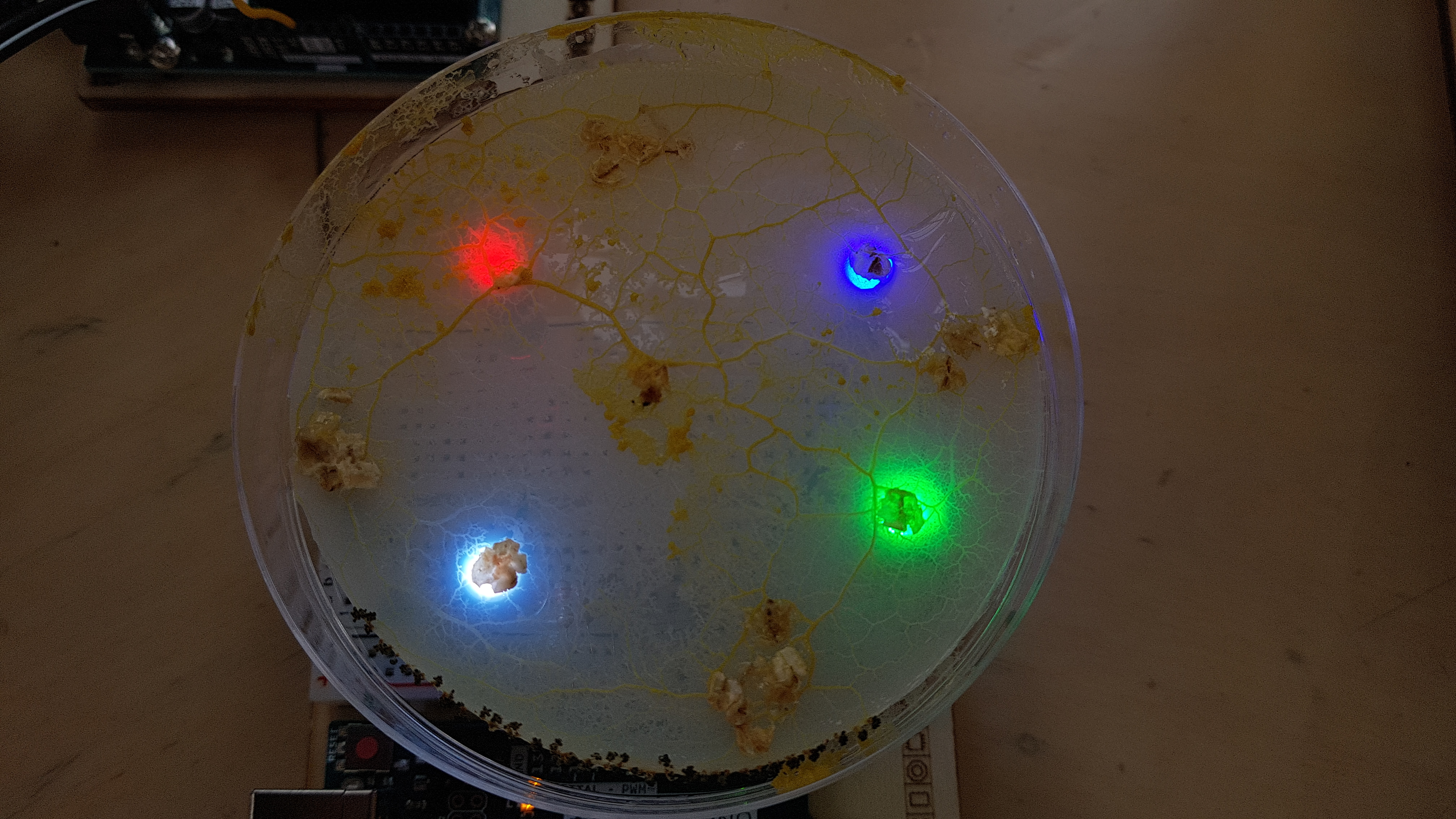
I found in the literature that one way of inhibiting the growth of slime mold is to use light, however there was no mentioning of what kind of light. So with and Arduino and a breadboard I made a light test setup. The colours from left to right: Green, Blue, Red and White.
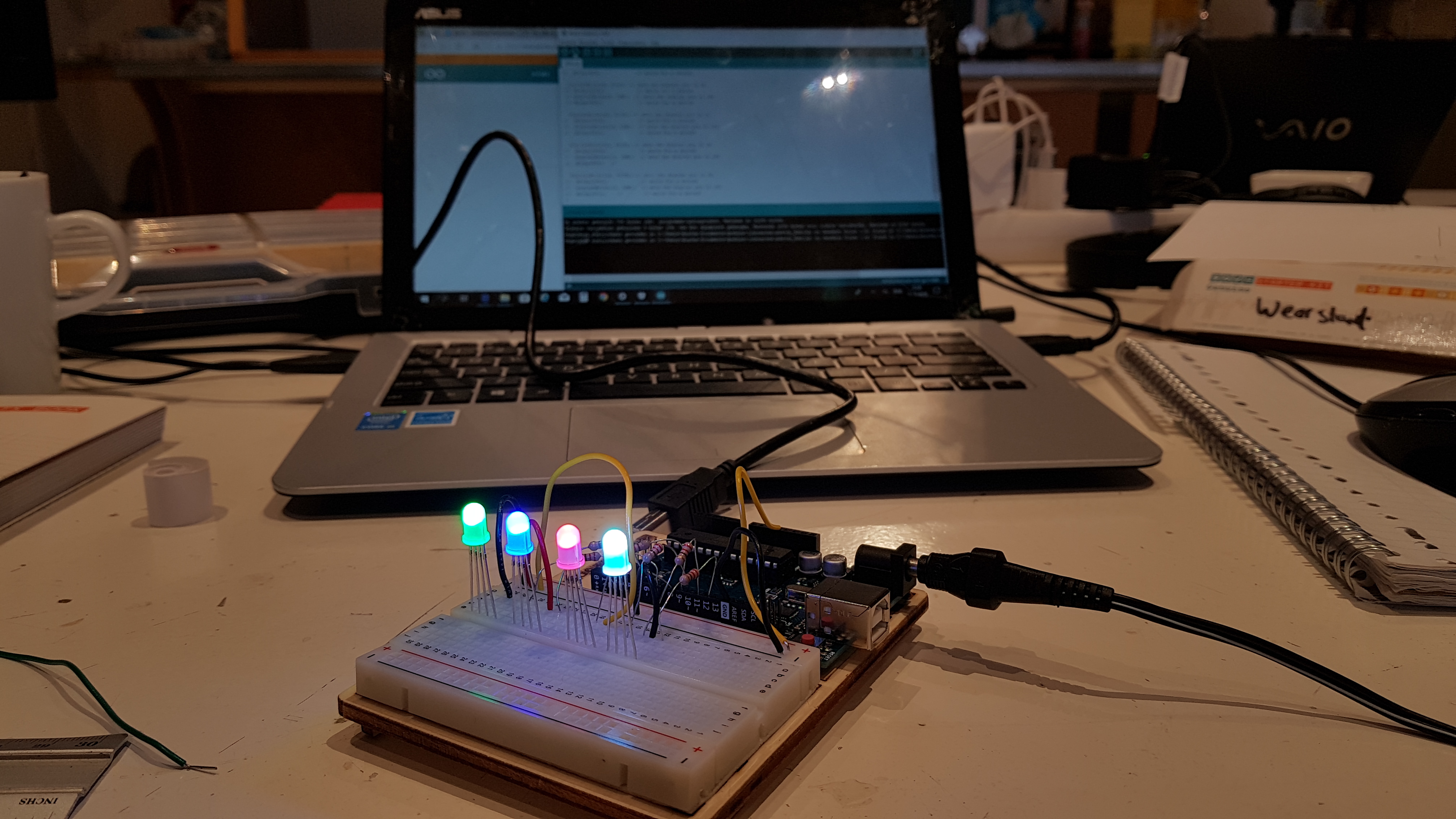
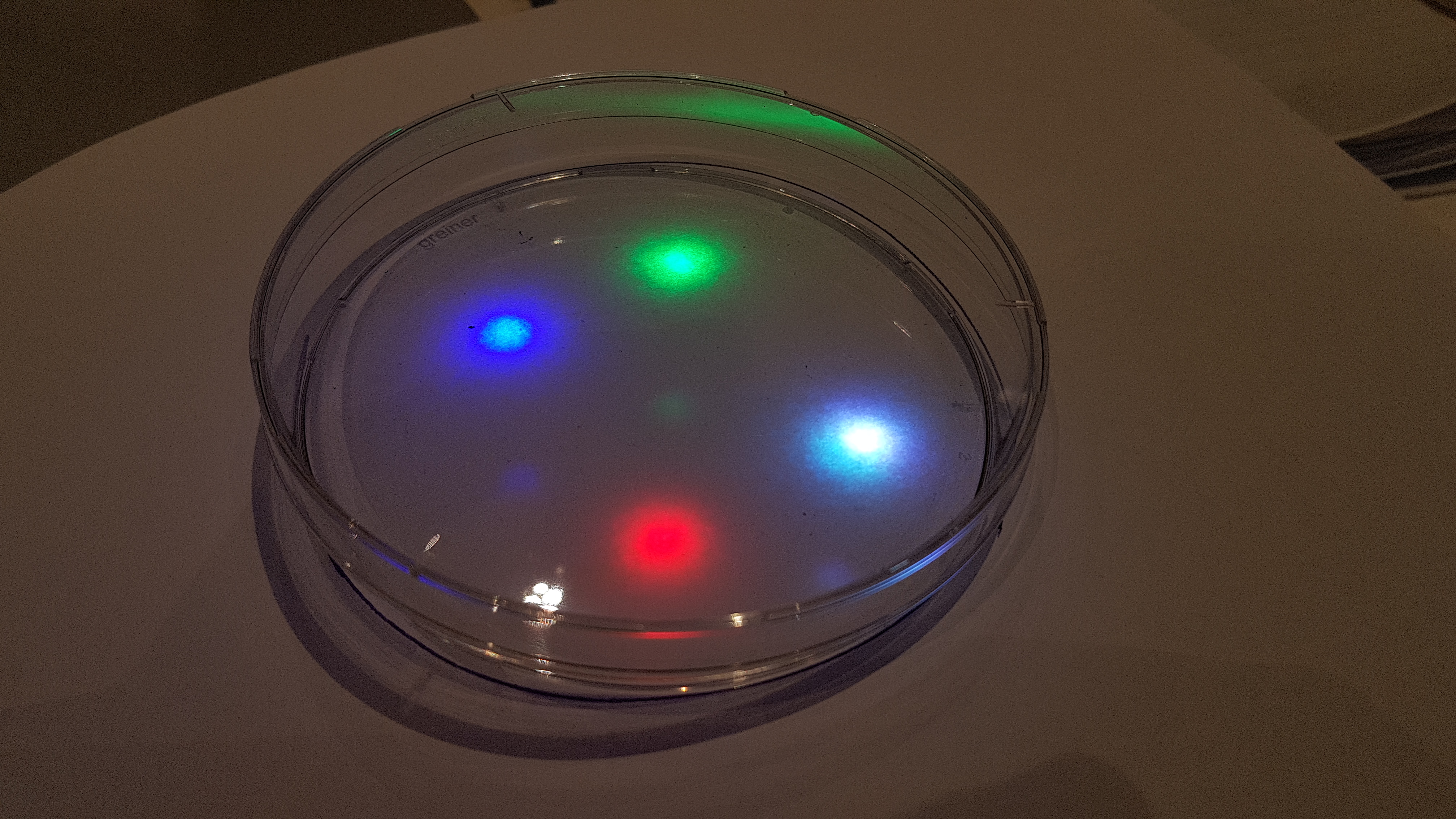
I placed the Slime Mold with 1 oatmeal flake in the centre of the petri dish, encouraged with the growth in the holding Petri dish and in order to have as little light absorption without any agar, surrounded with the 4 lights and 4 food sources placed beyond the lights. The entire setup up was placed in the sterile hood.
Light inhibition grow test results
1 day later this was the result, NO GROWTH!
Light inhibition grow test #2!
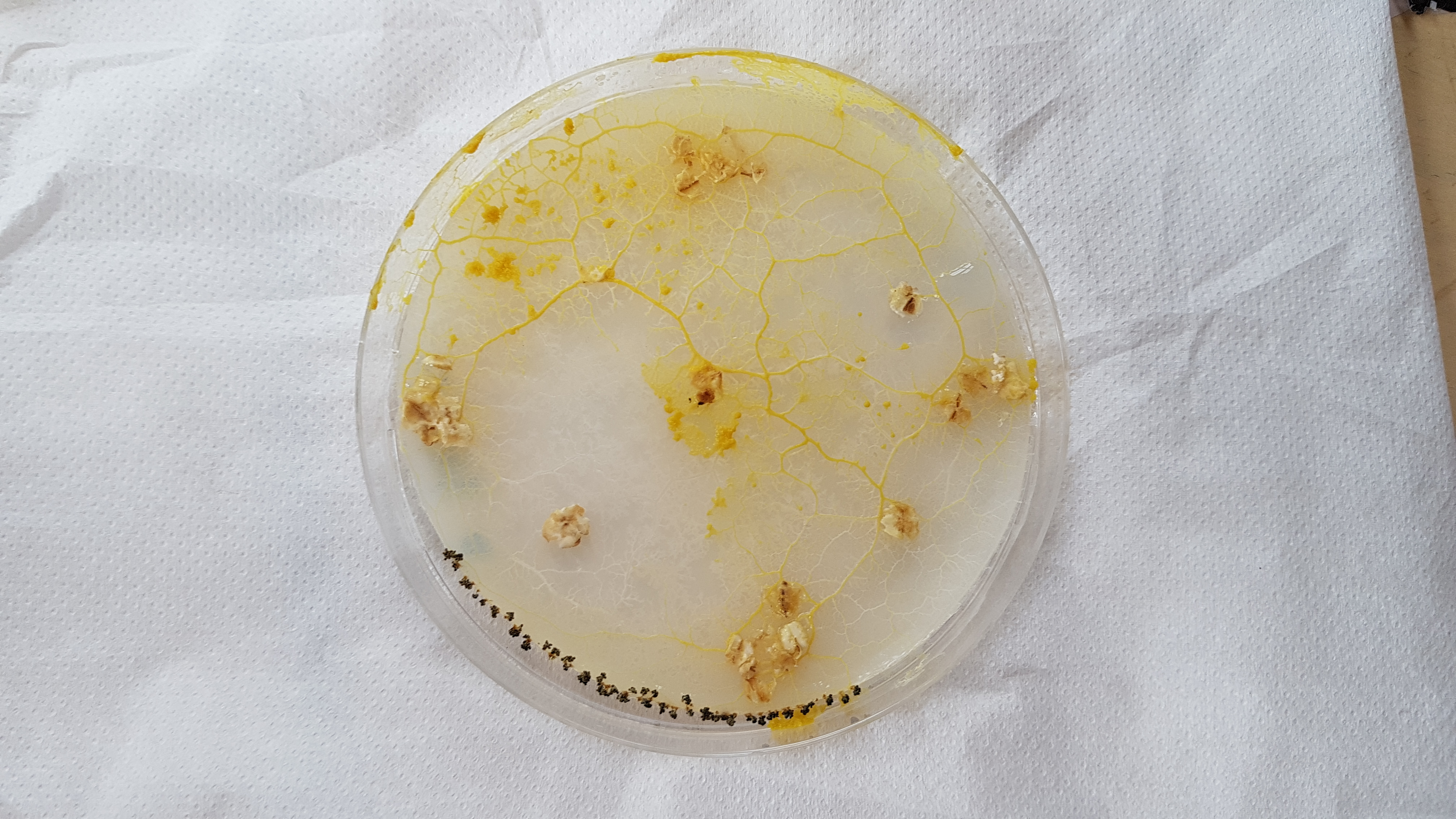
So I build an identical light setup, did very thing the same, however this time with a low nutrient agar!
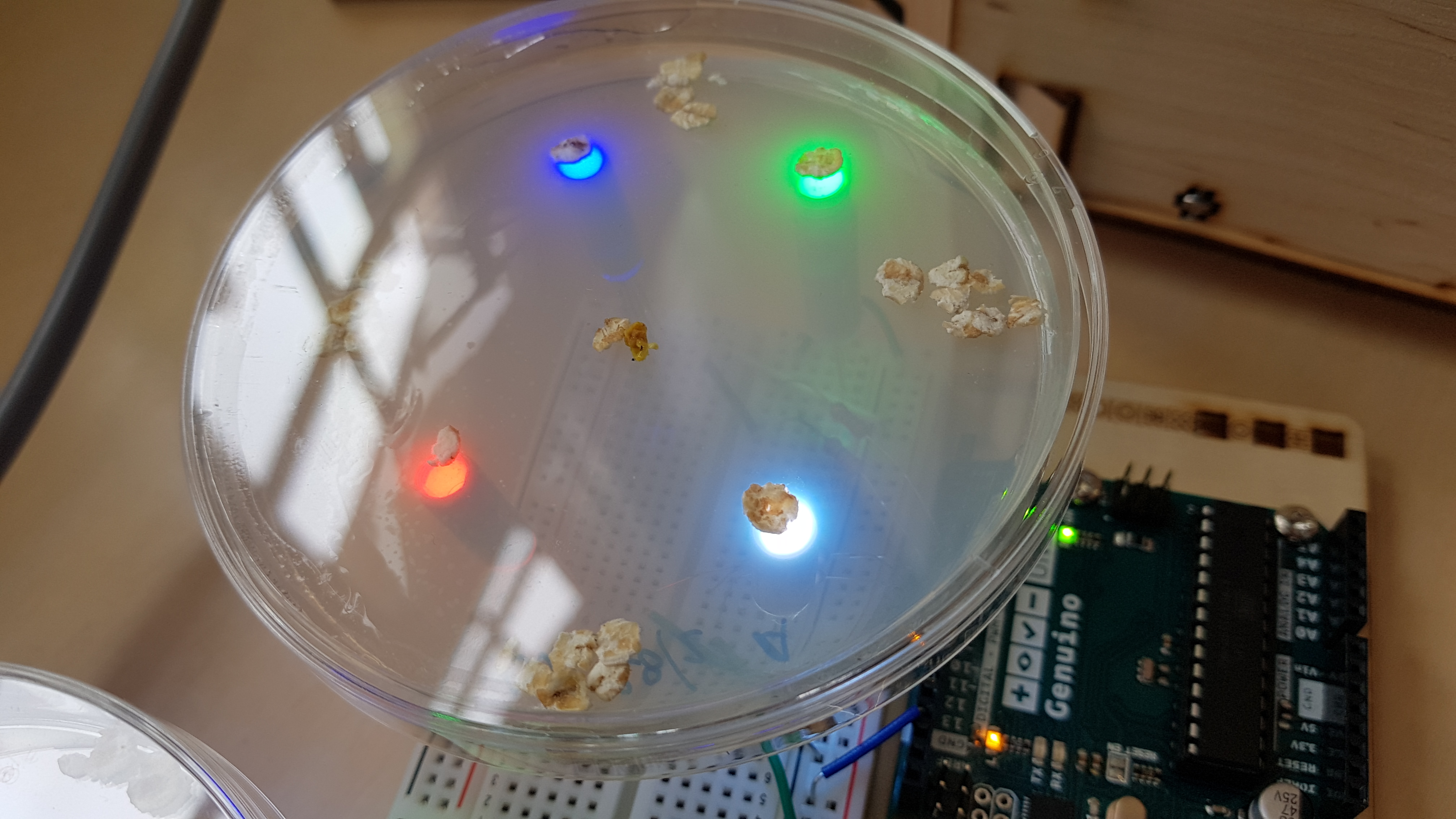
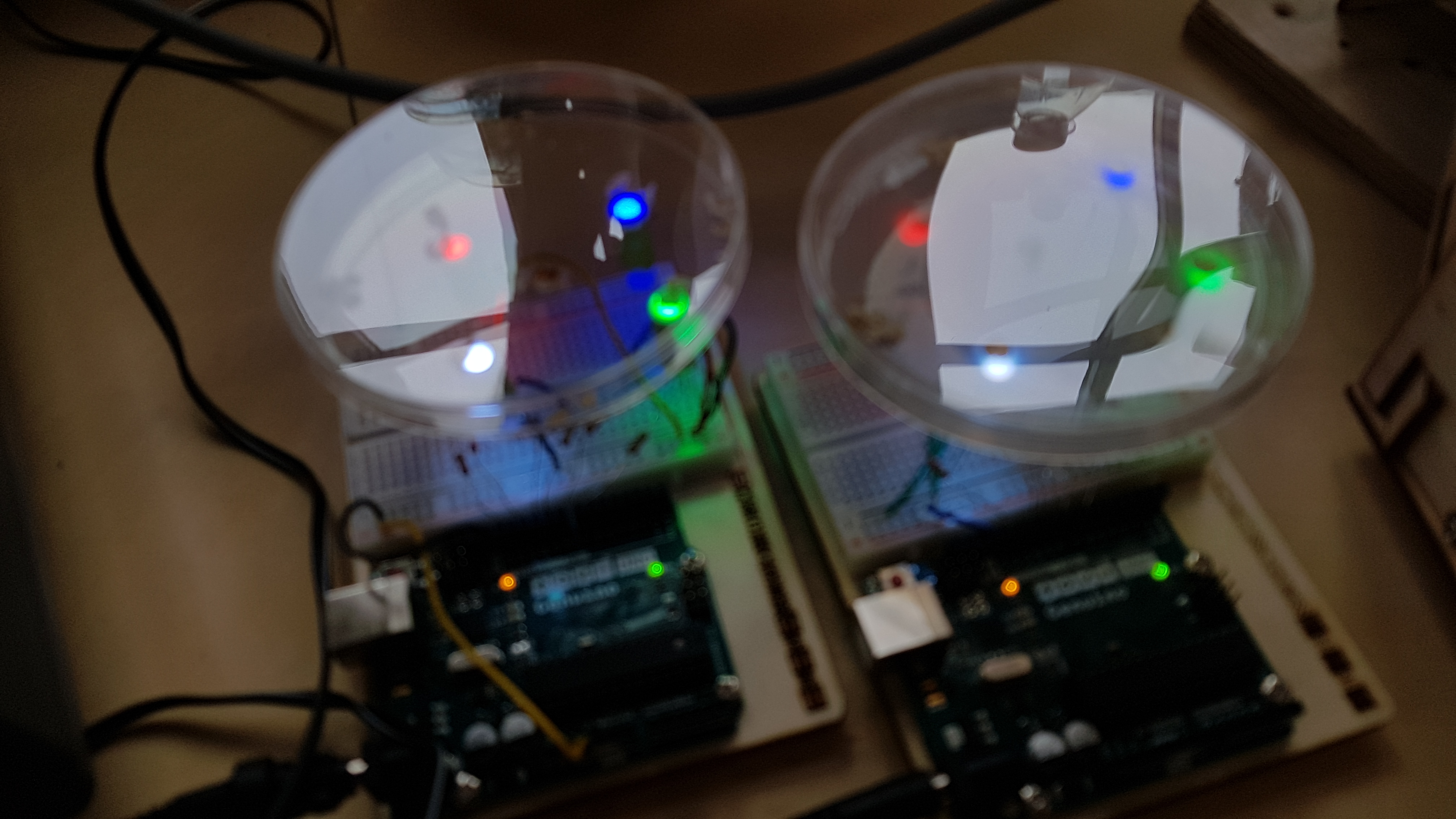
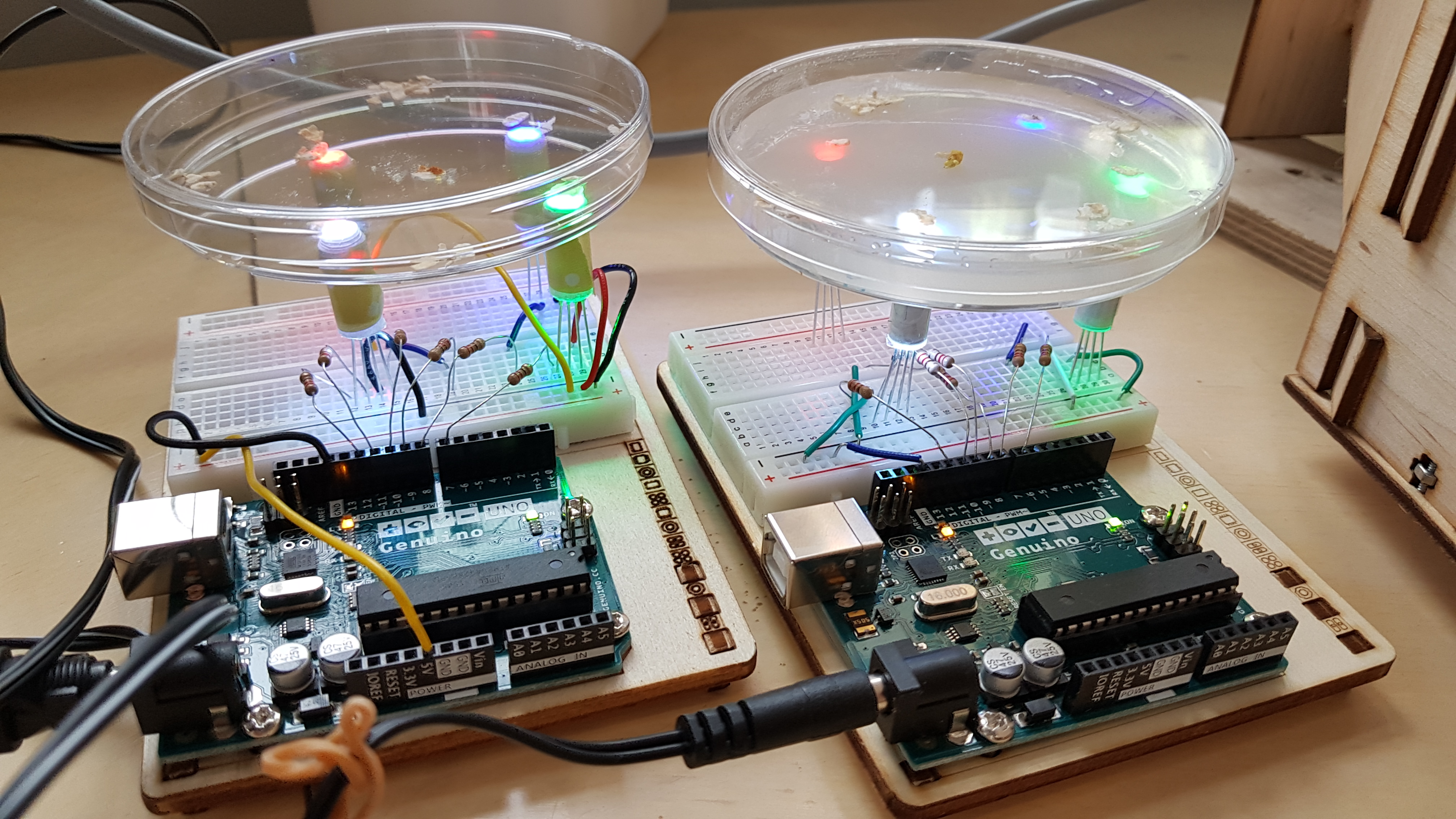
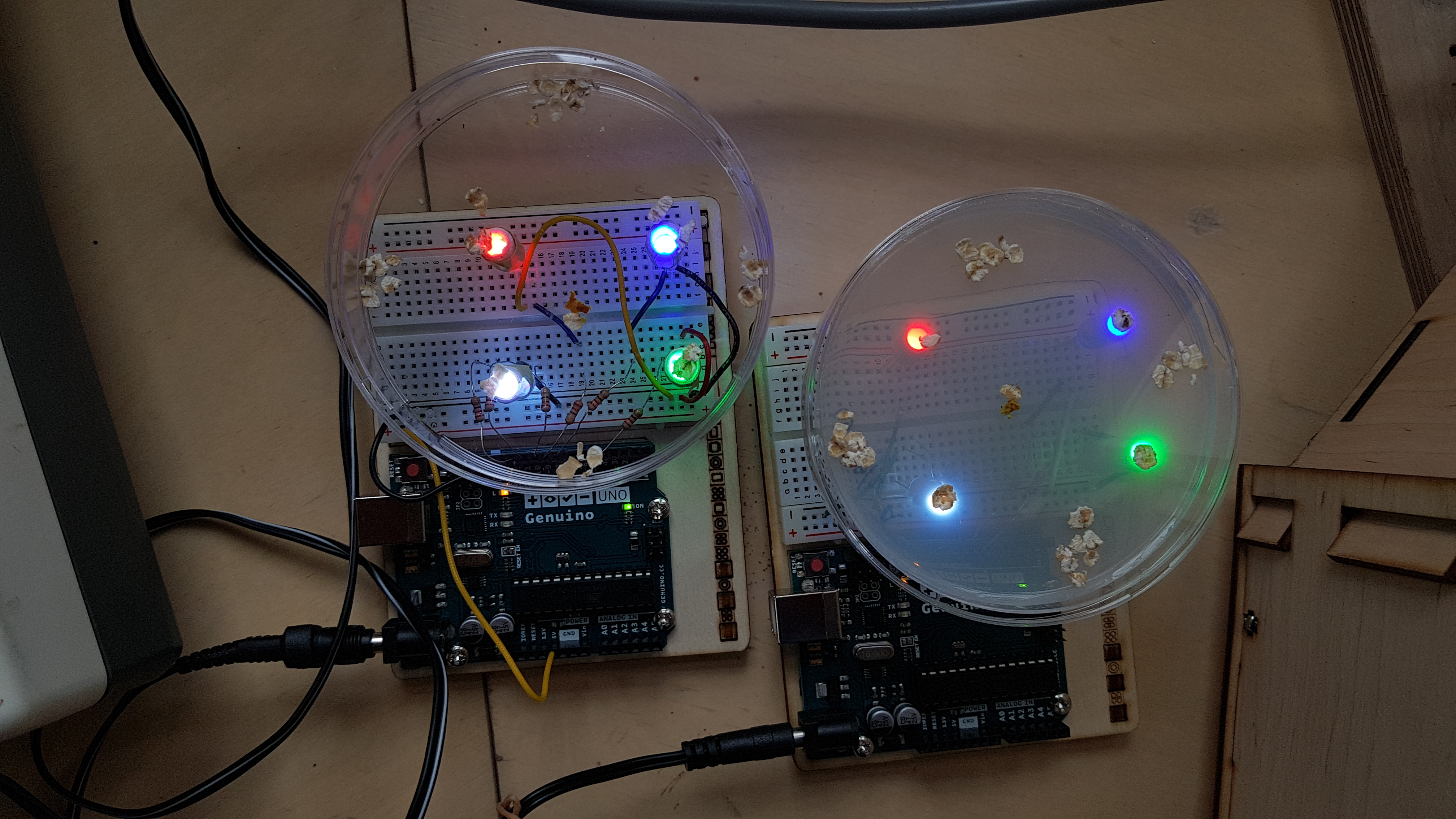
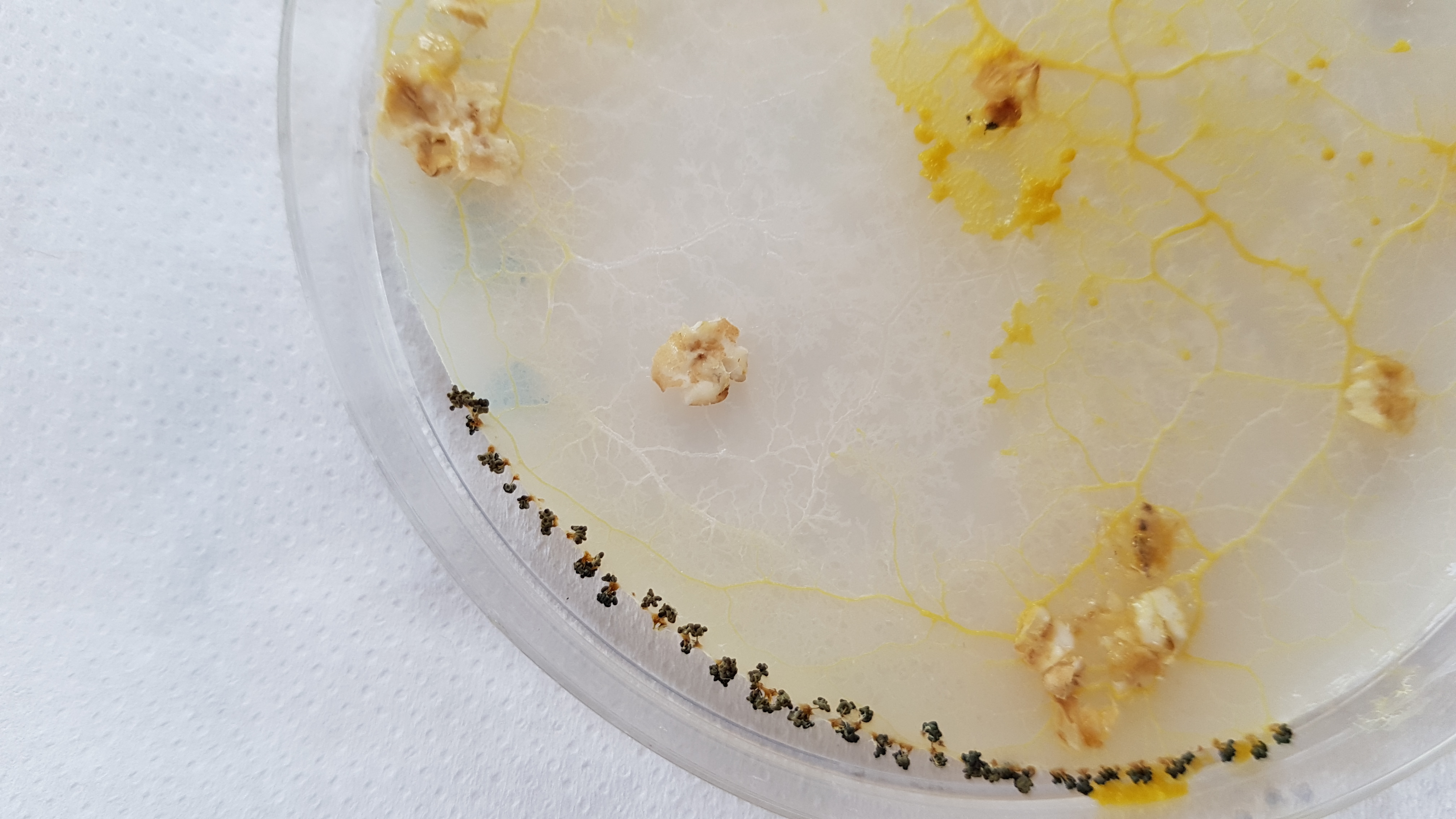
Light inhibition grow test #2 results
This time there was result, the White light had inhibited the growth of the Slime Mold.
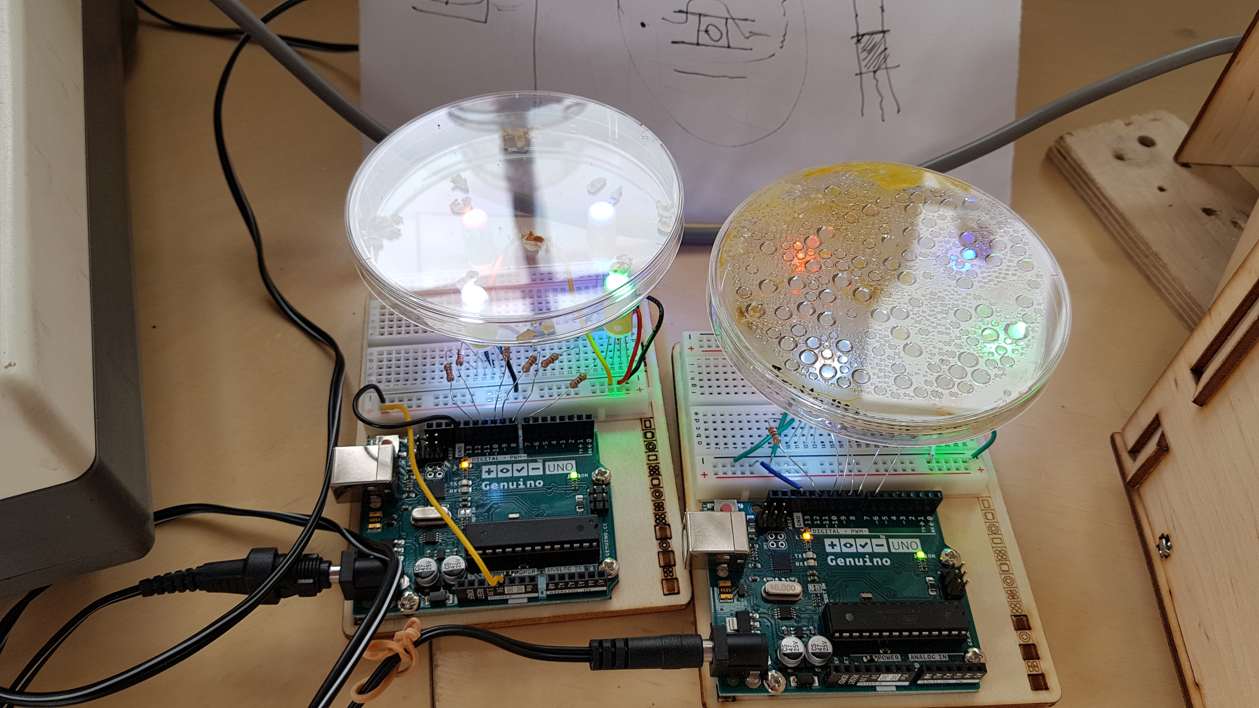
So now I knew I could try to build a single Logic Gate
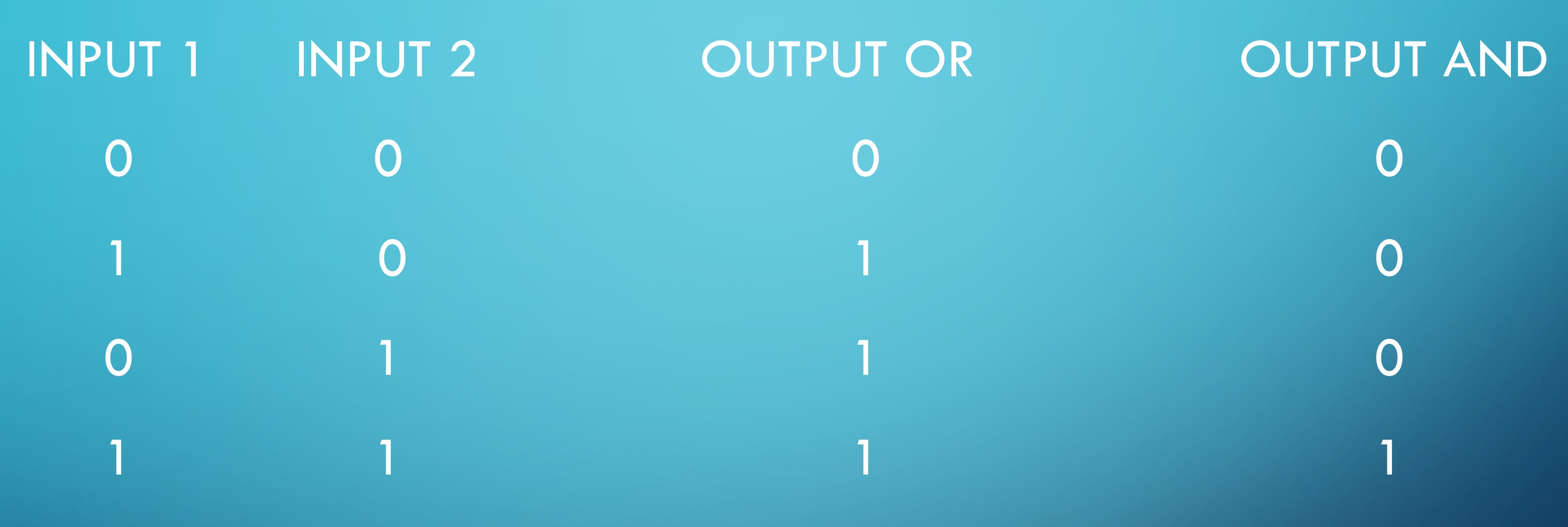
Logic Gate Truth Table
How does a Logic Gate work? The two most basic Logic Gates are the OR and the AND gate, both have 2 INPUTS and 1 OUTPUT. The behave as stated in the Logic Gate Truth Table
Prototype logic gate setup
Physically I didn’t want to build my first prototype Logic Gate in a Petri dish, so I came up this cardboard design, lined with Cling Film and then agar pour in as medium. With this setup I could light directly from above.
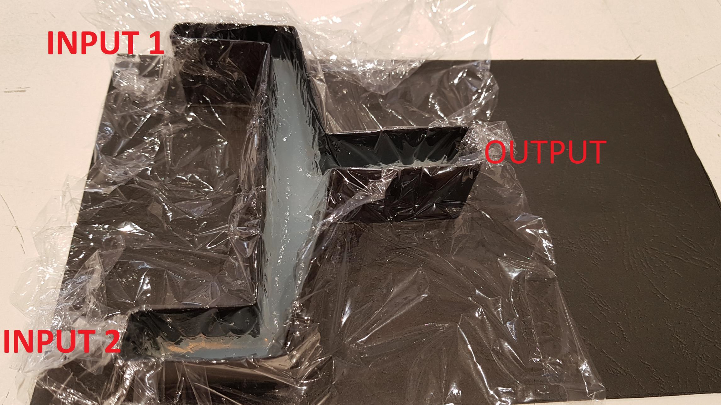
Logic Gate with cardboard spacer for the breadboard light setup.
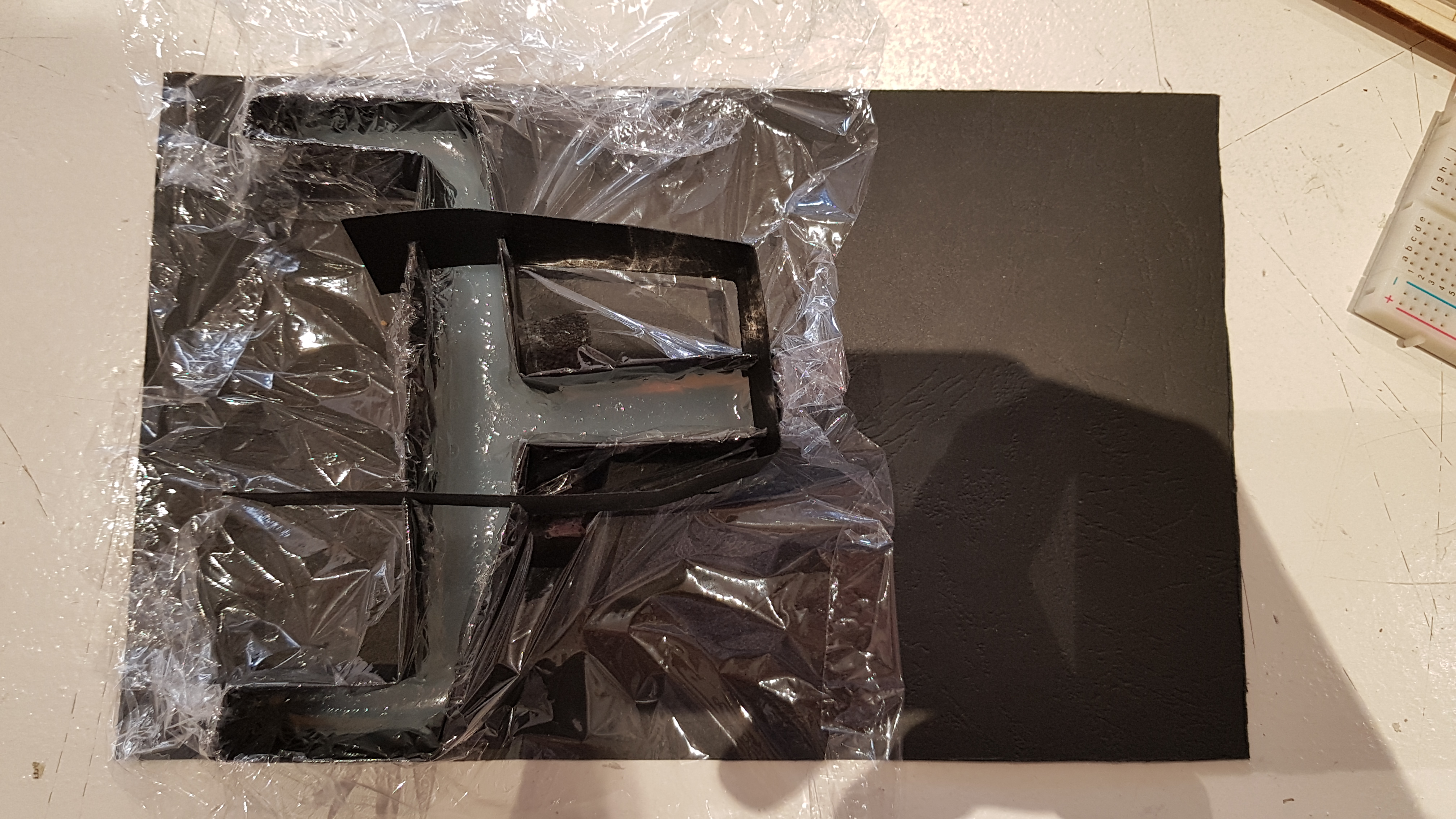
Lighting scheme was setup to block INPUT 1 nearby and INPUT 2 far away, creating a hybrid OR+AND prototype Logic Gate
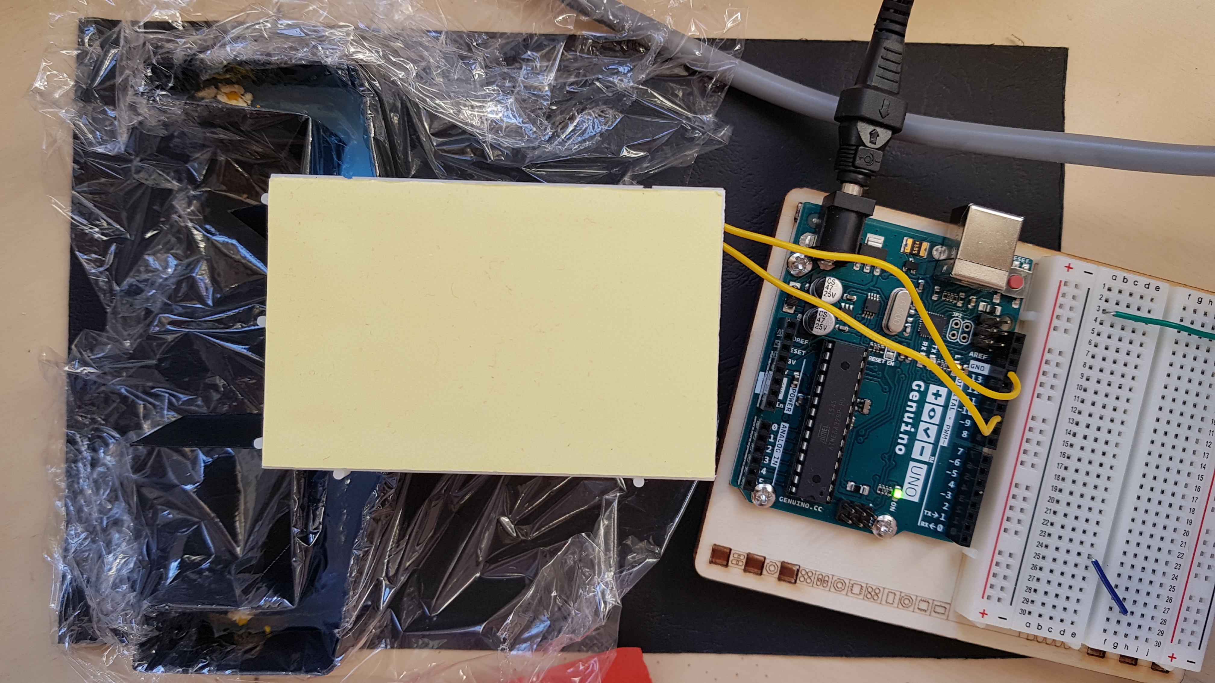
The two Slime Molds at their starting points
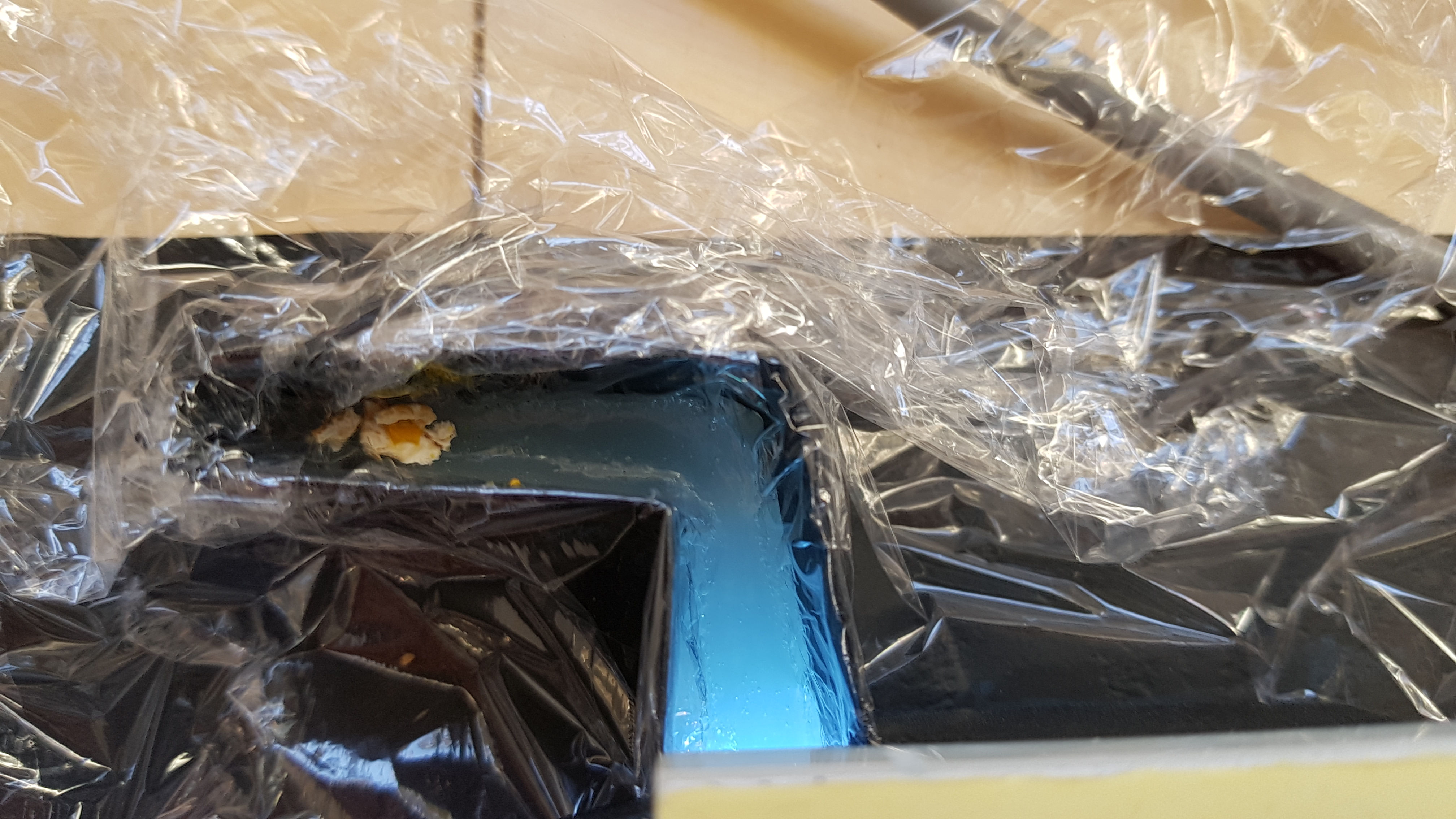
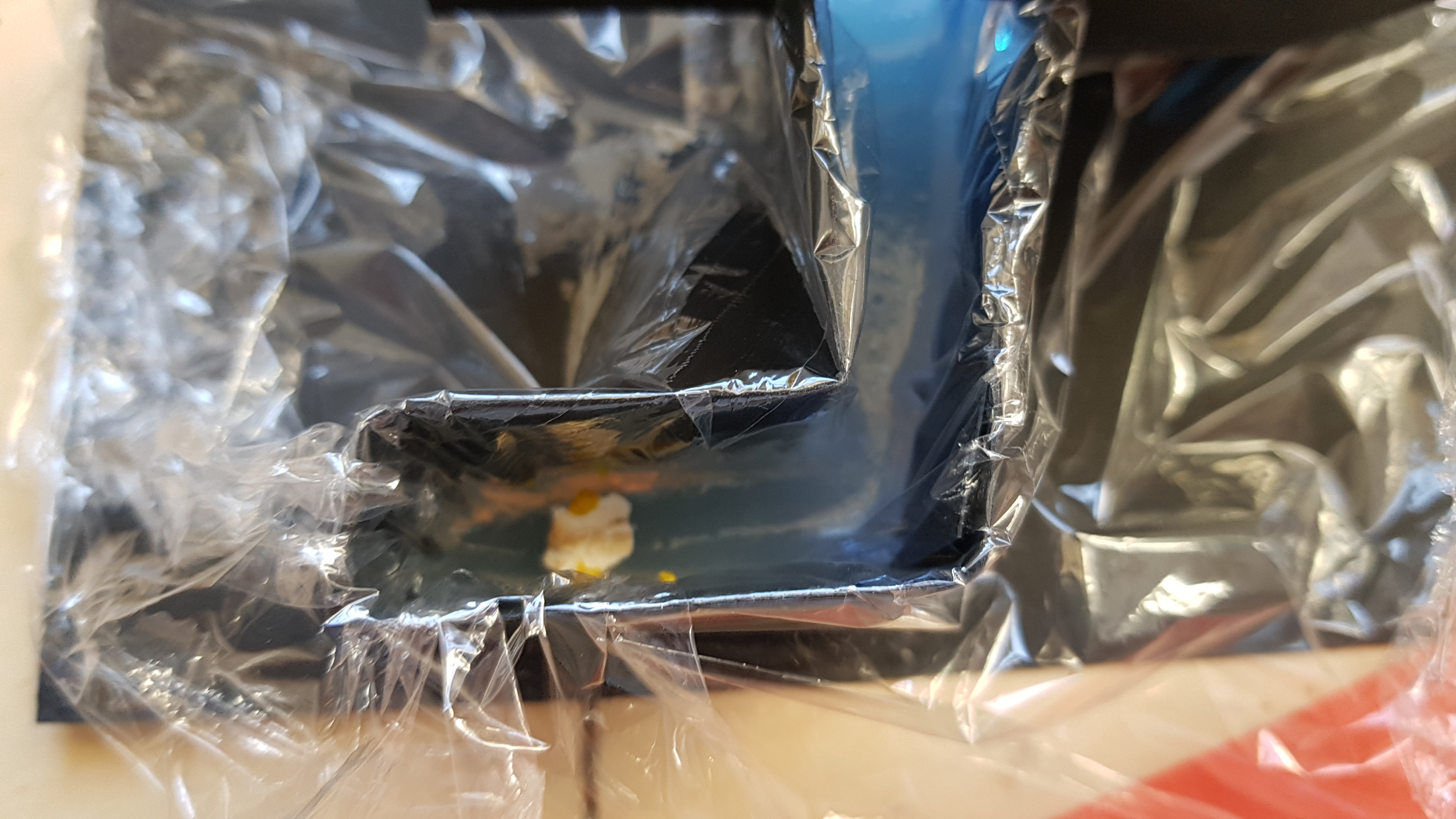
Prototype logic gate result
The grow pattern was how I was hoping it would be.
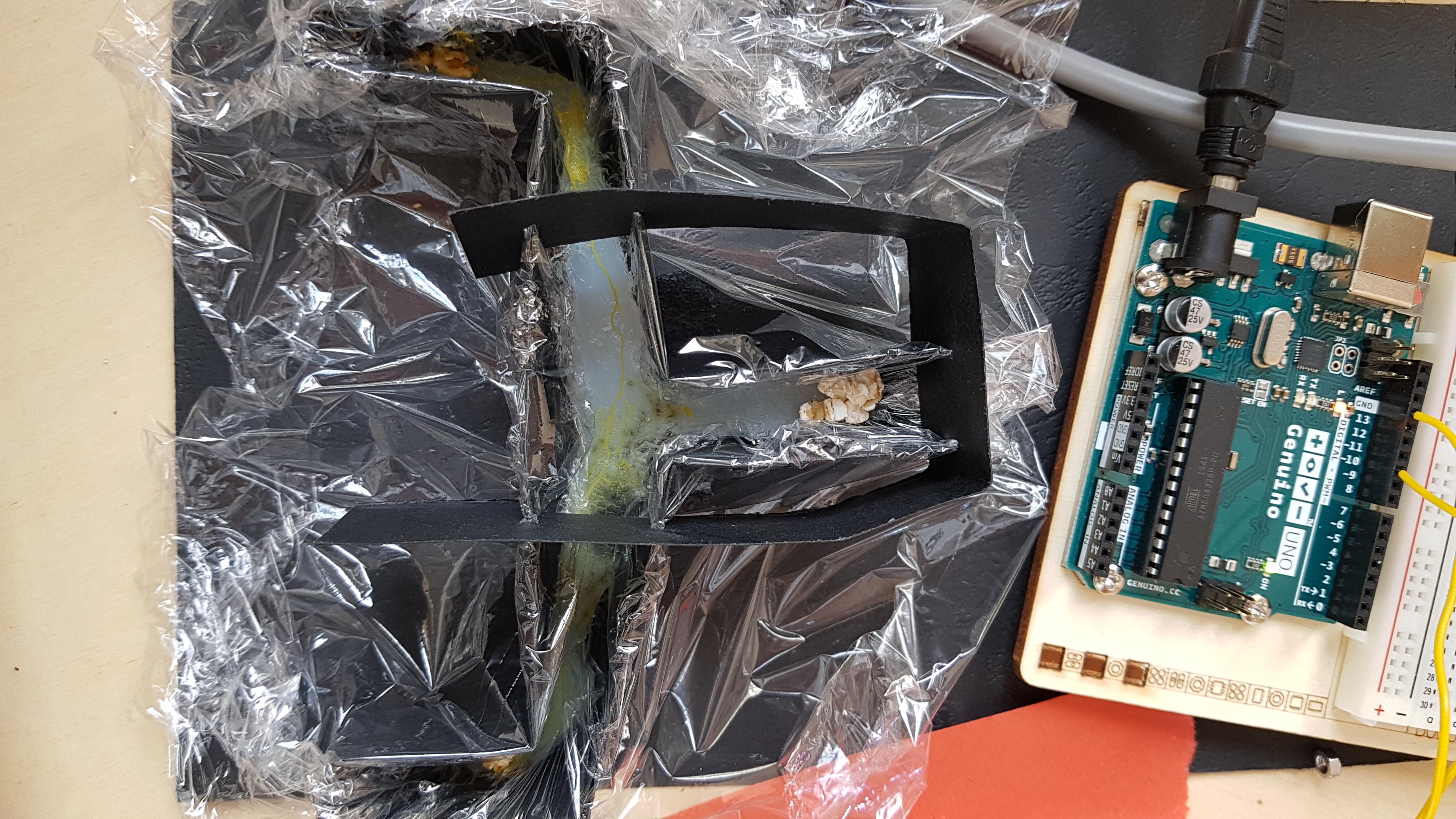
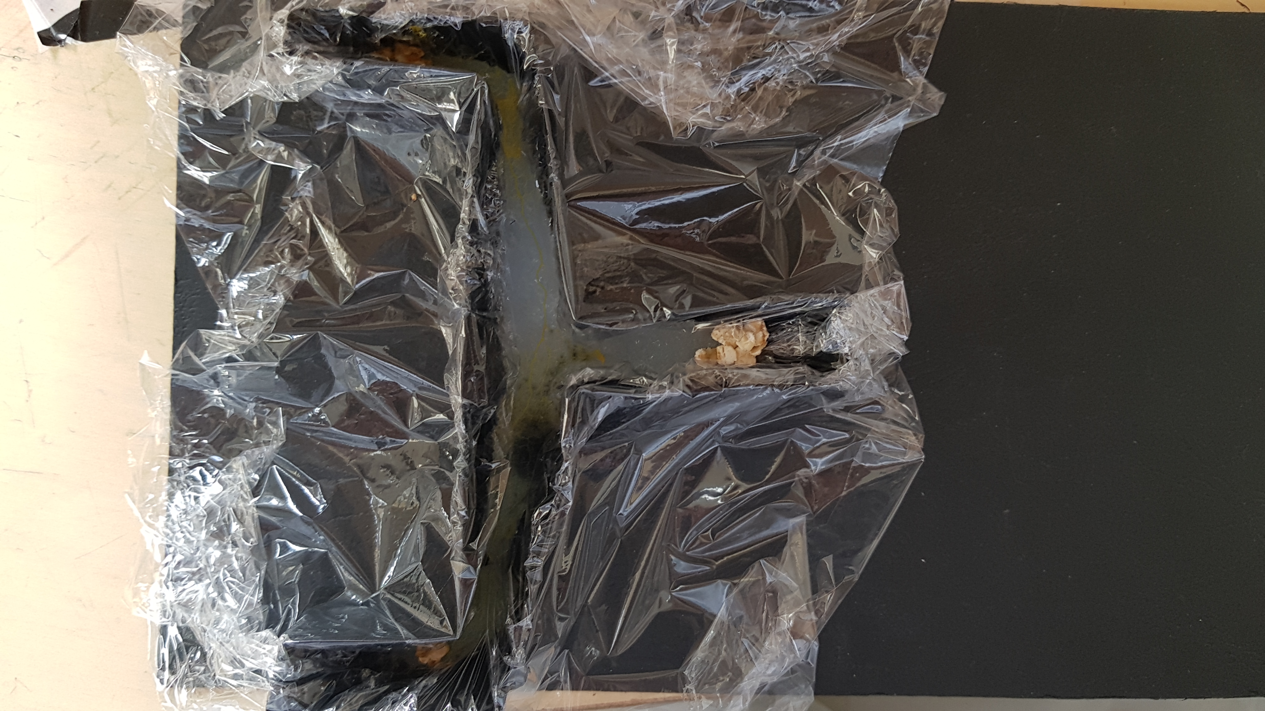
Detailed pictures, on INPUT 2 there was also a foreign black mold visible
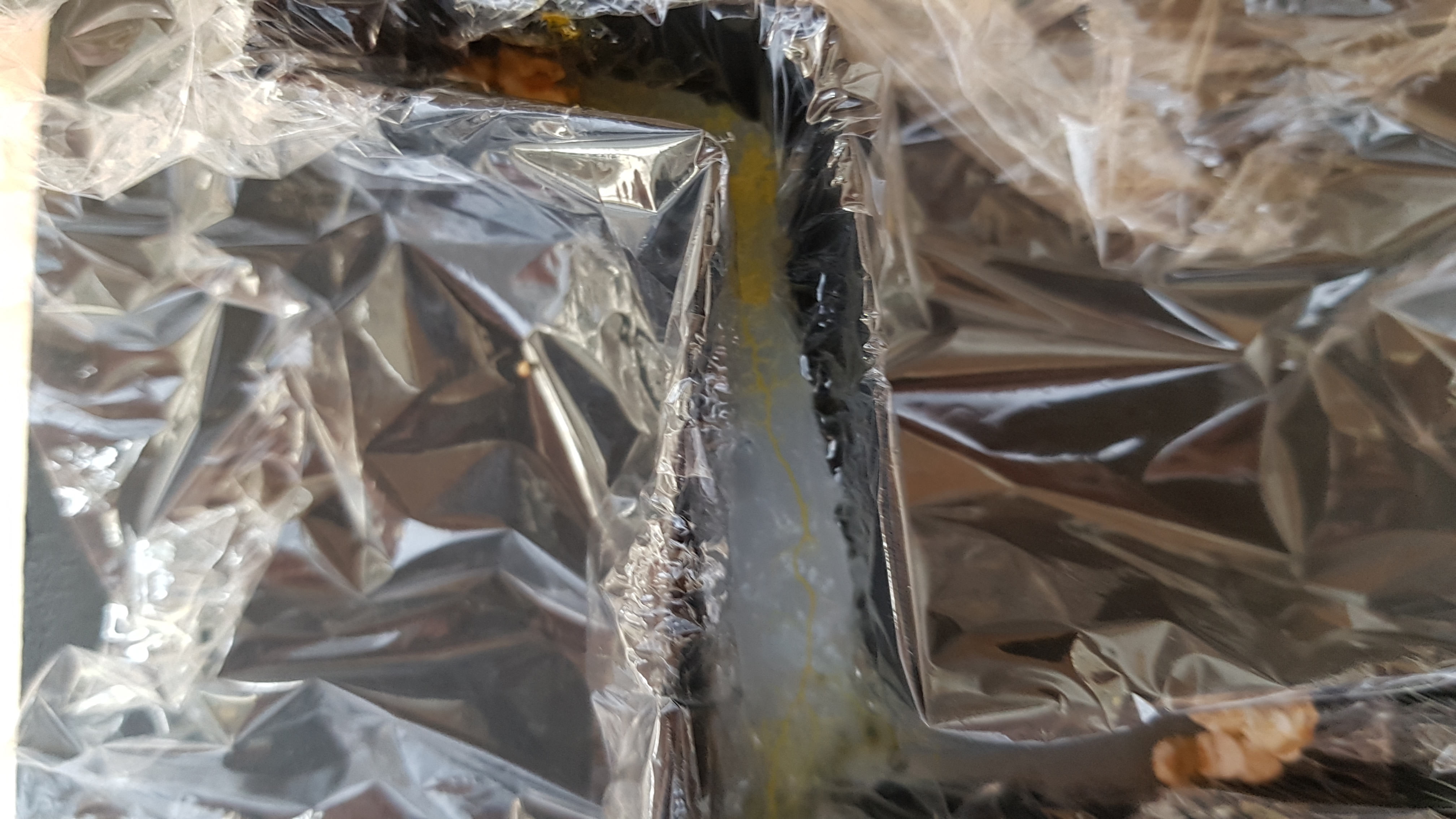
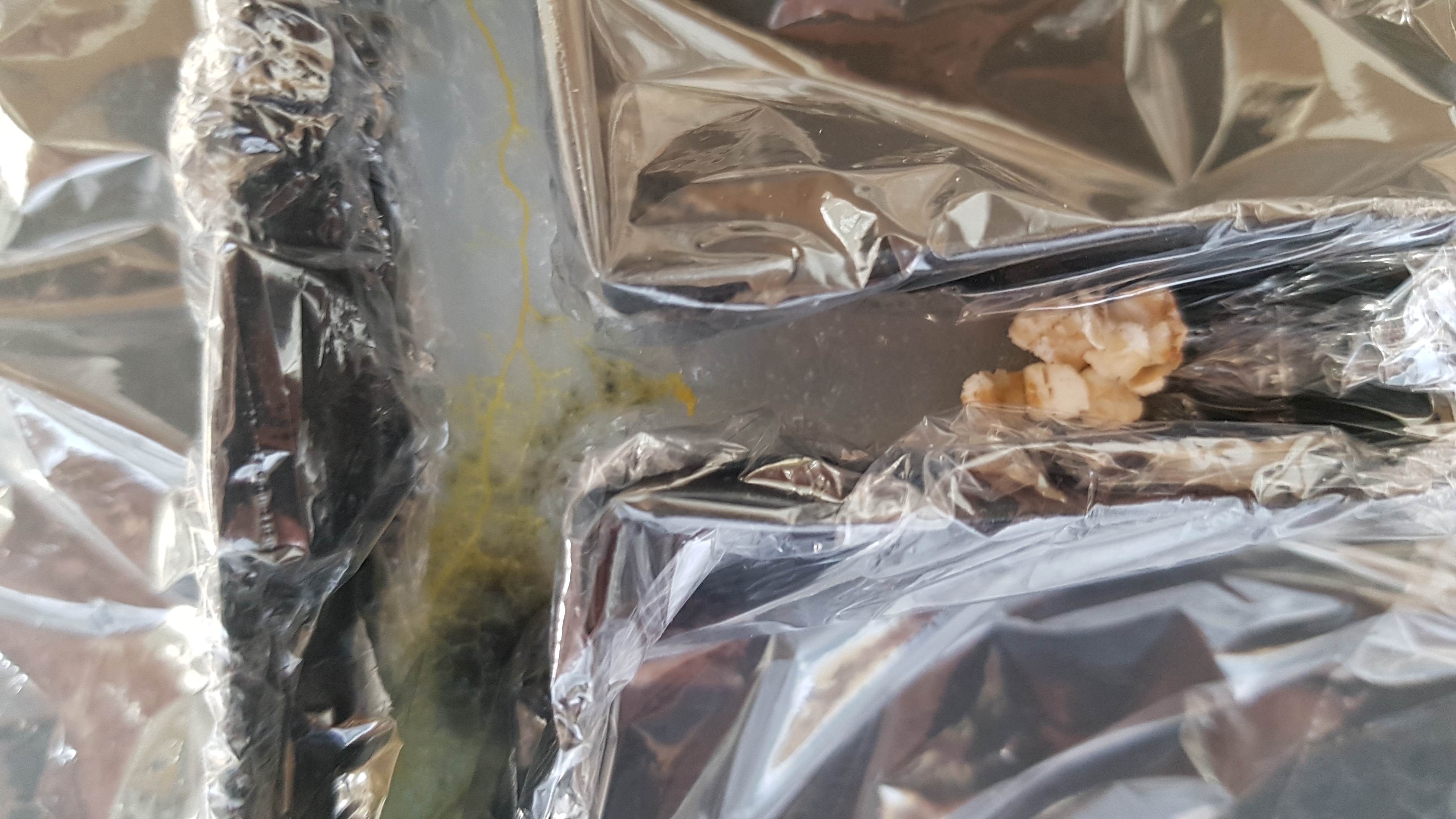
Prototype logic gate result +2 hours; light switched off
In order to test if the Logic Gate could work dynamically I removed both light sources for 2 hours. This was the result.
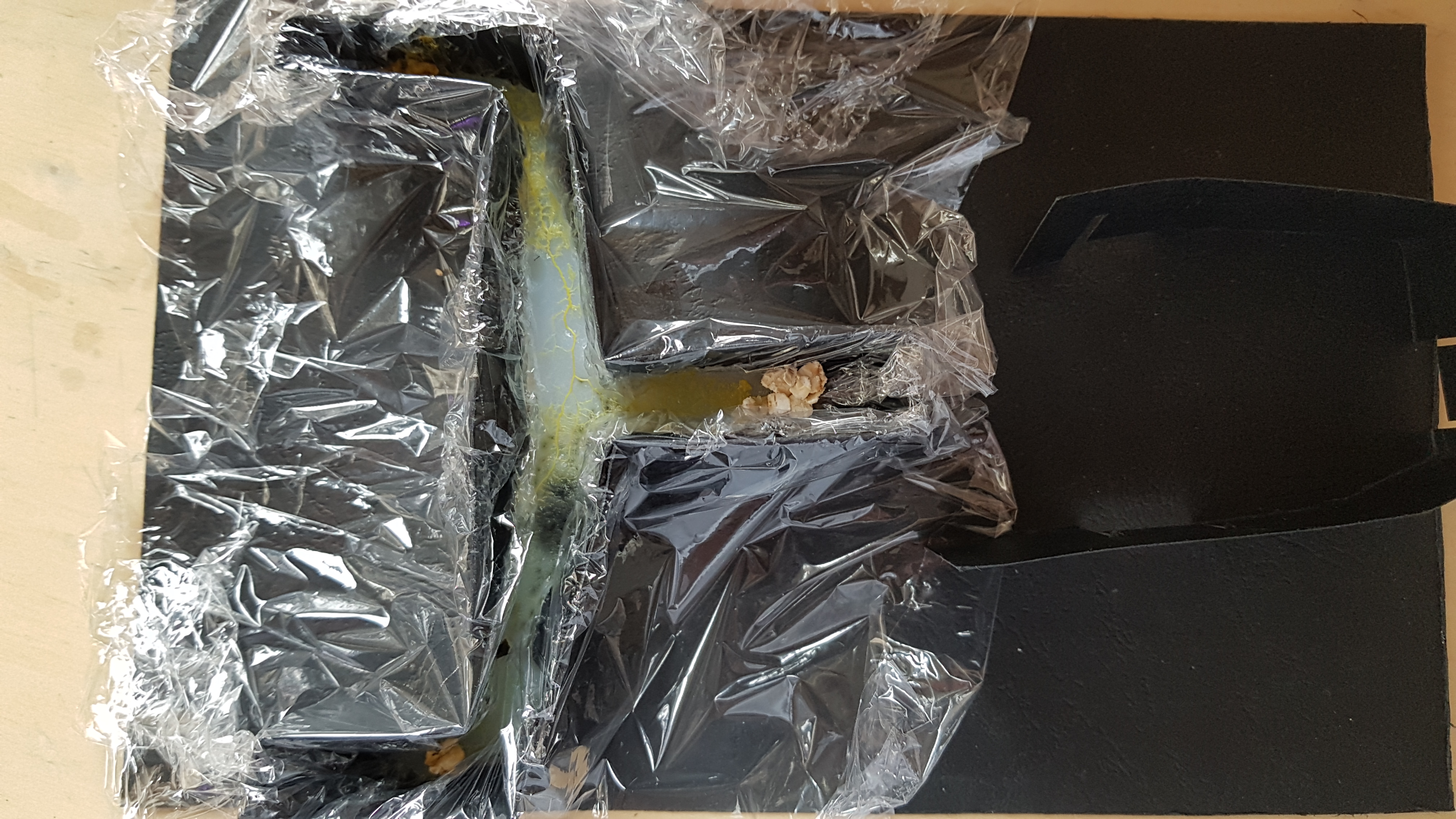
Detailed pictures
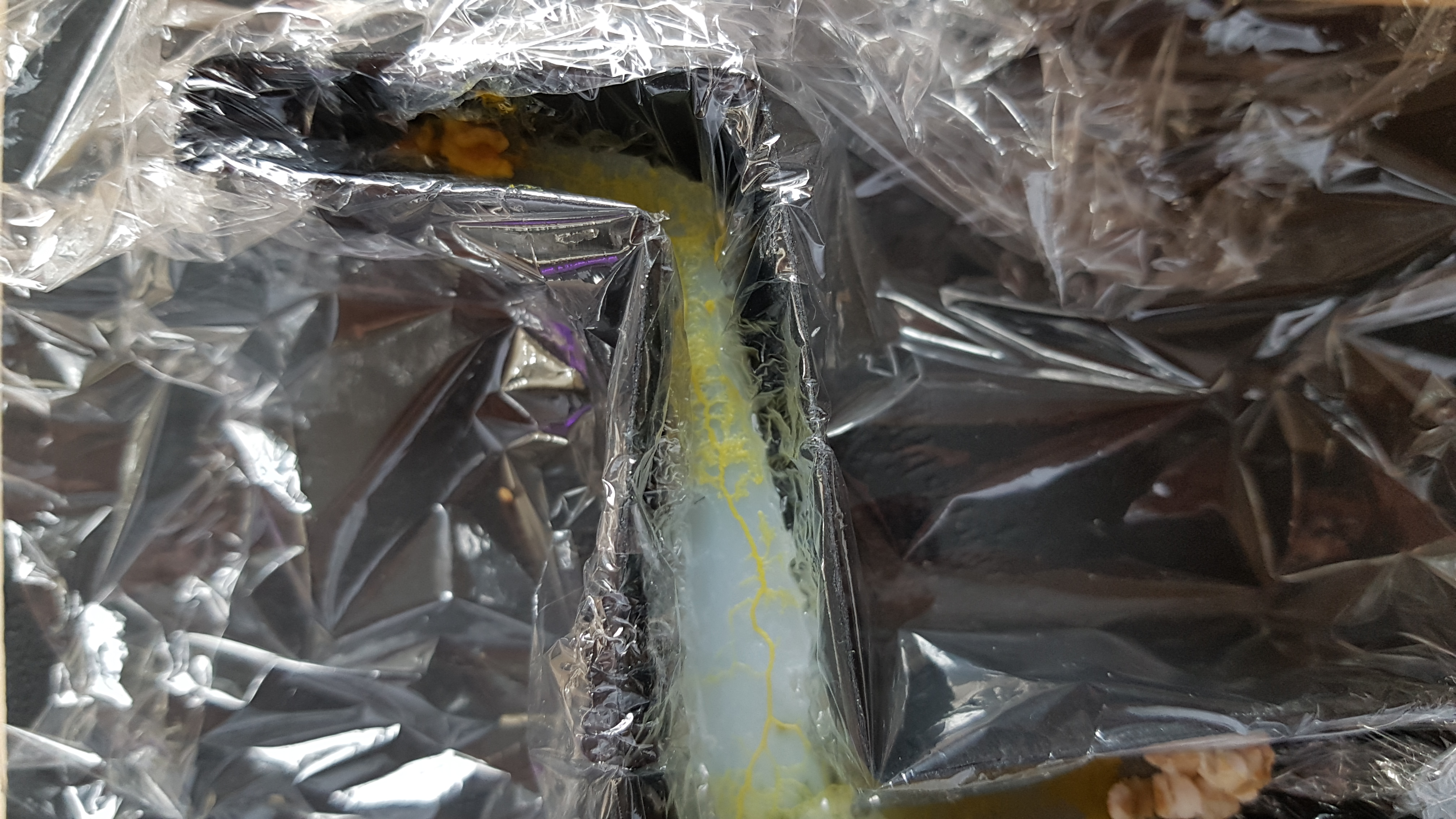
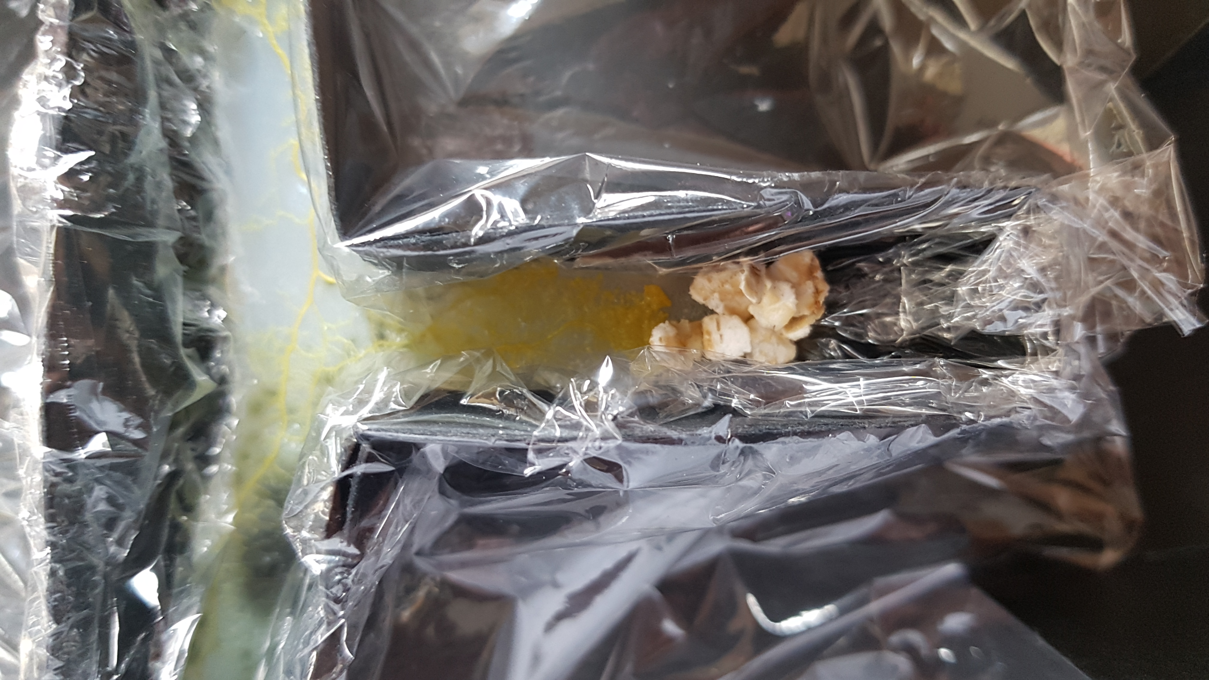
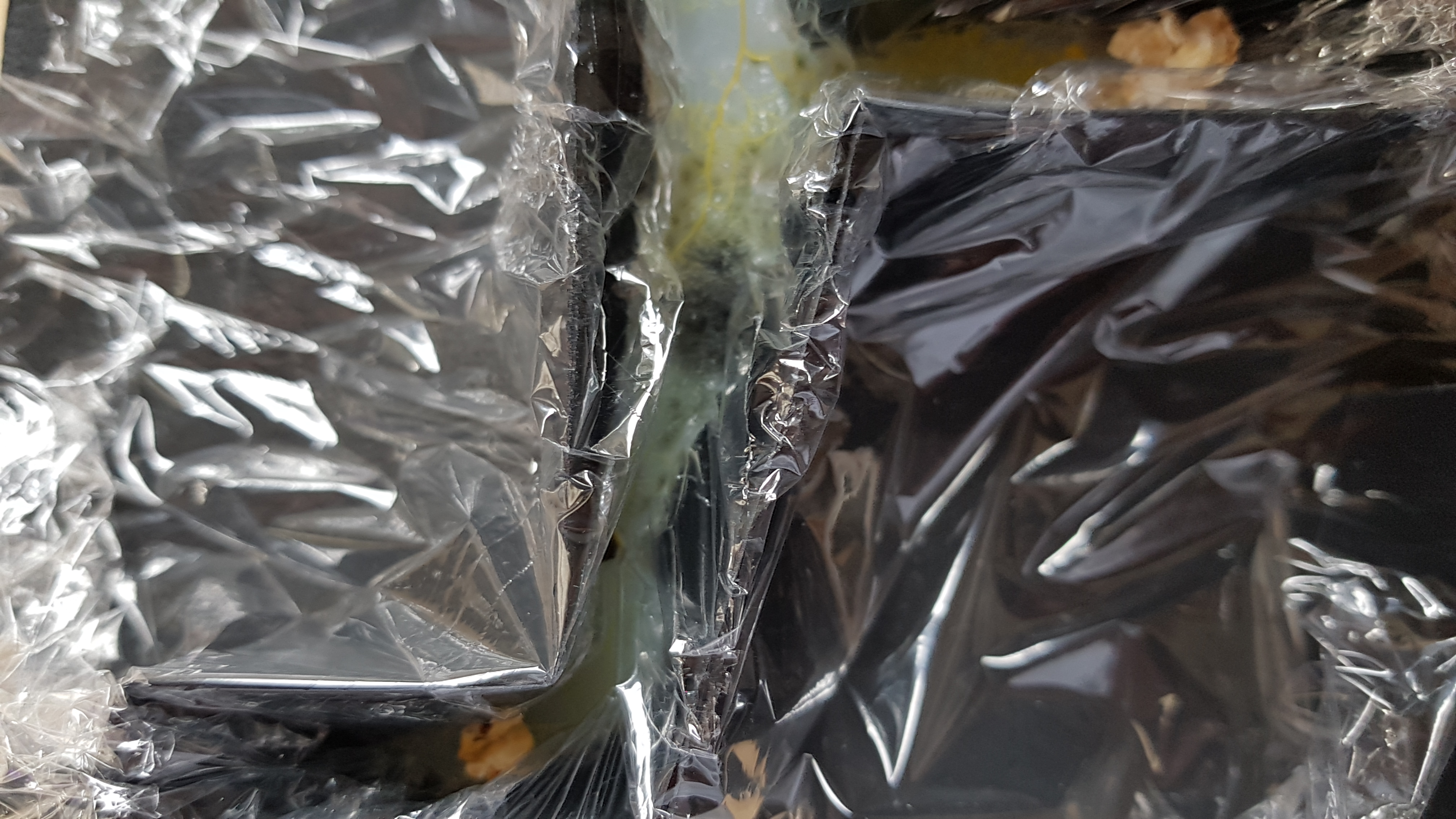
Now there was visibly growth in both areas previous been lighted
Prototype logic gate result +4 hours; light switched back on
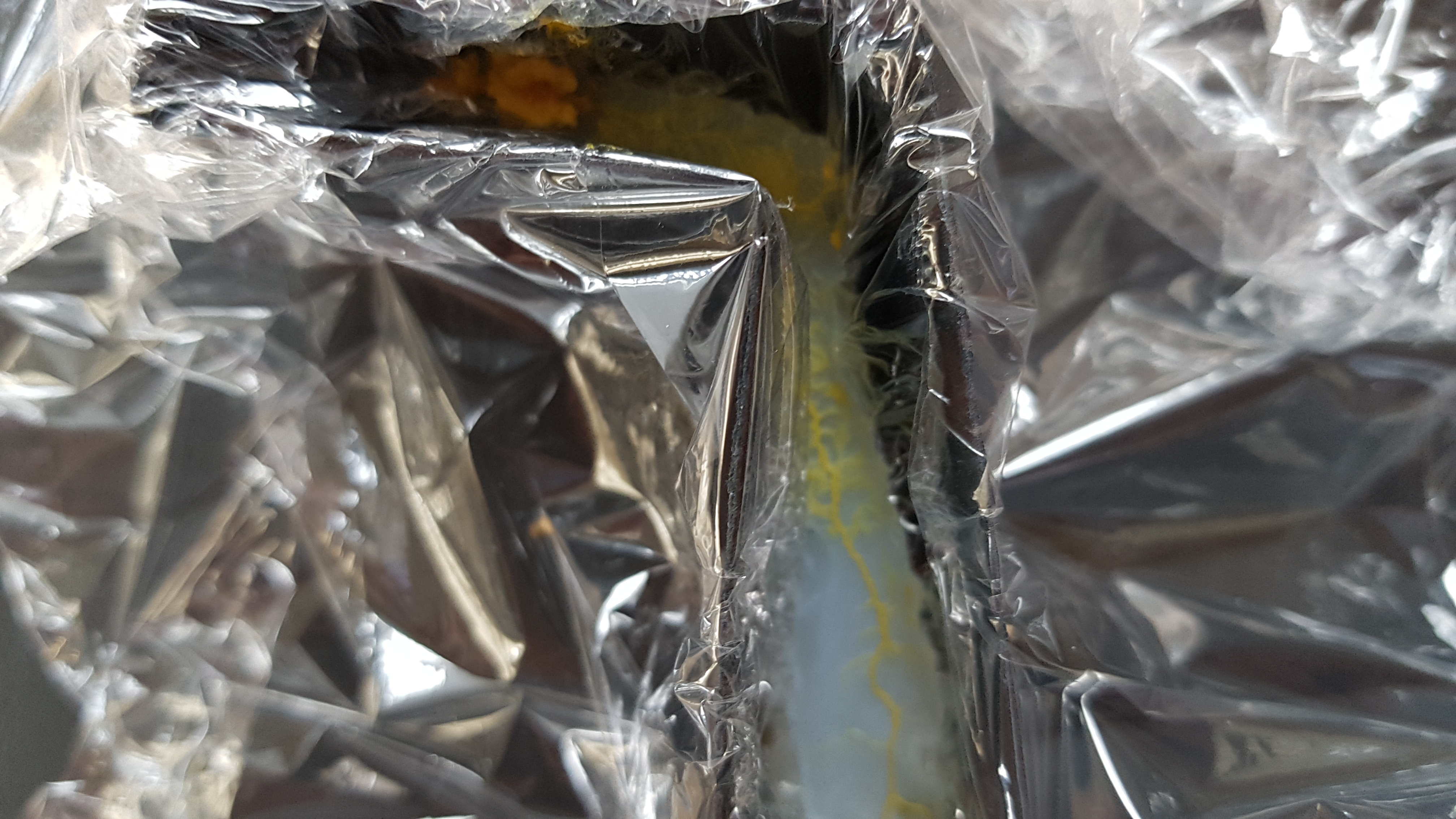
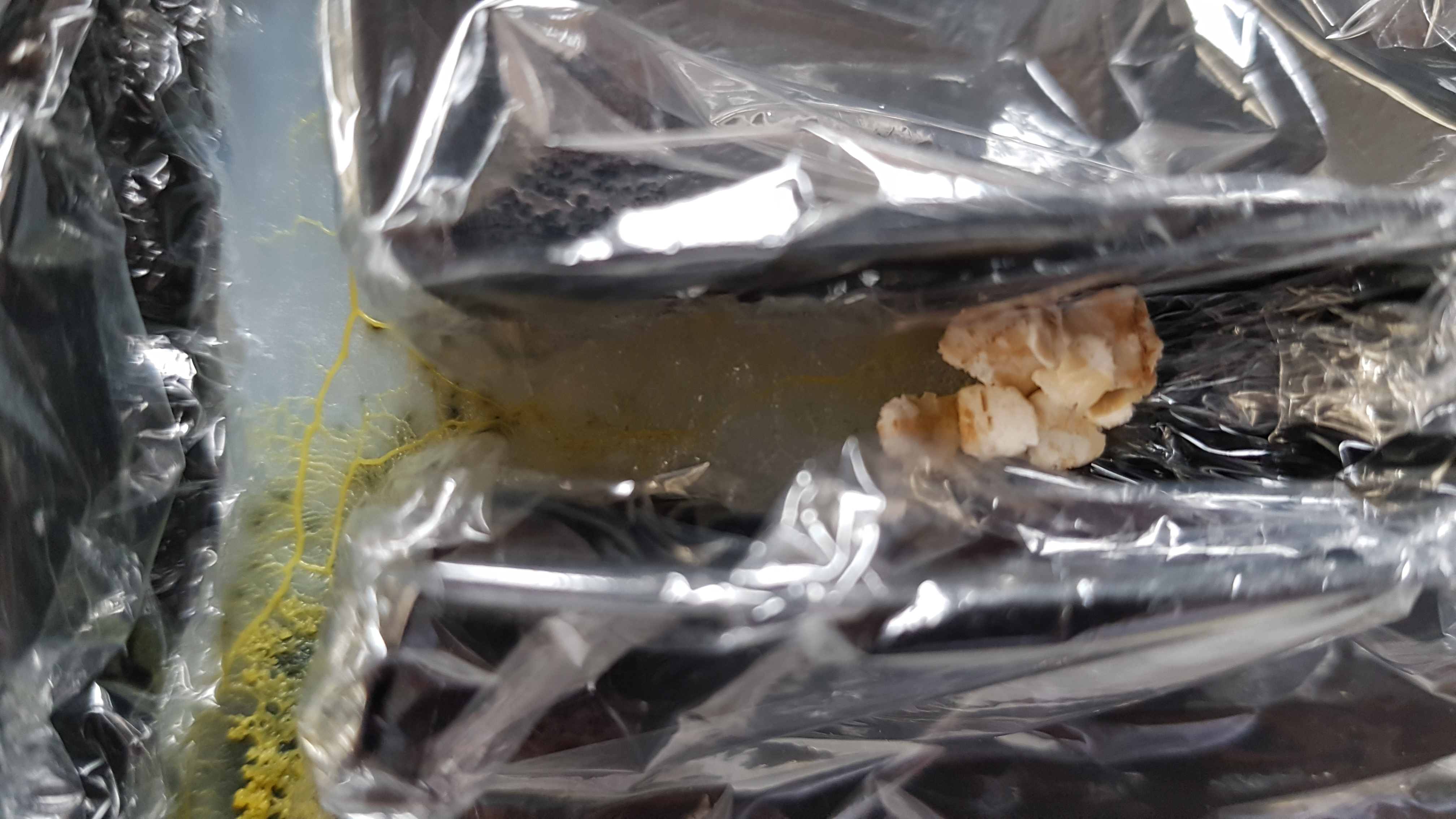
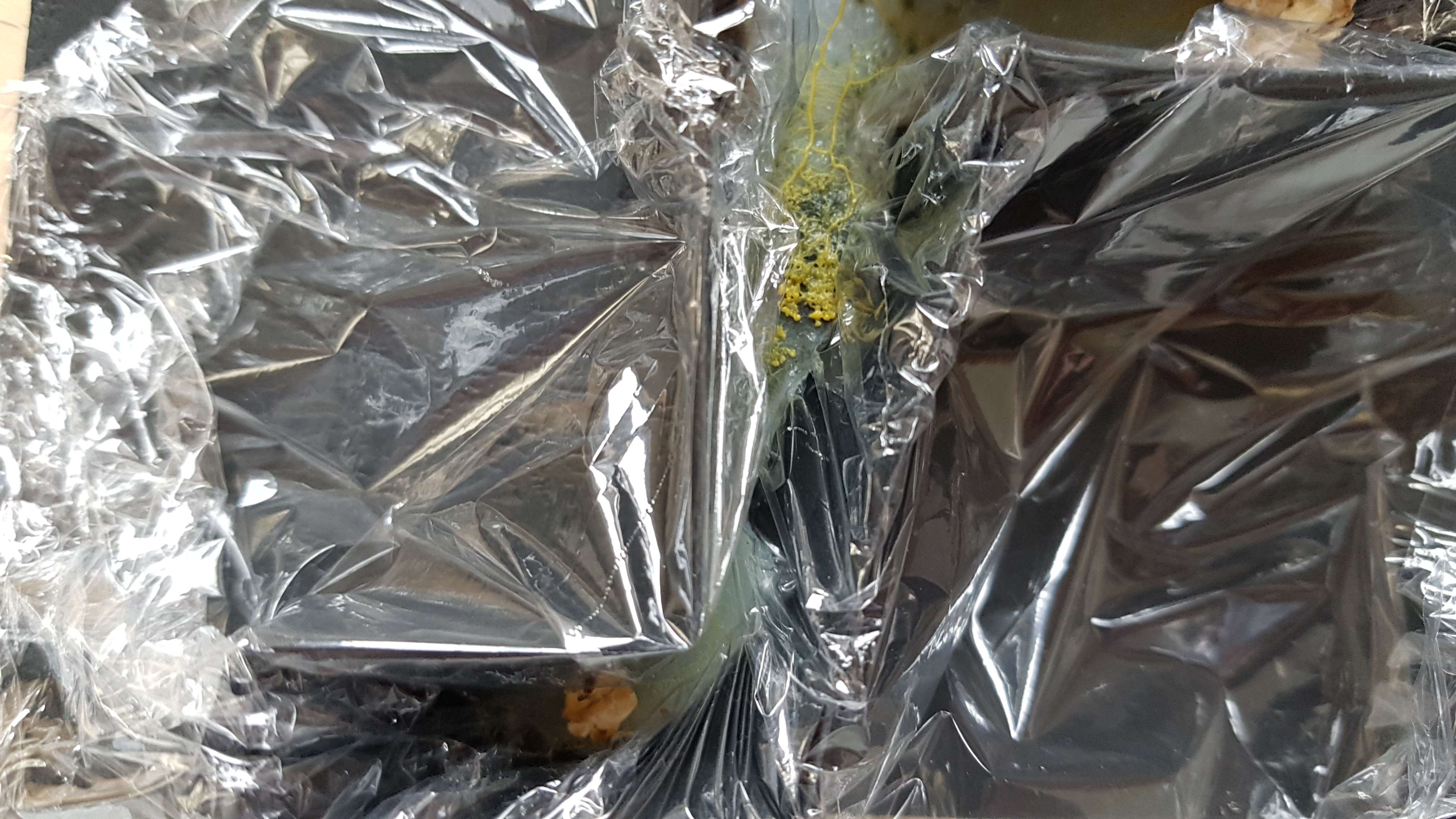
Now I reinstalled the lights as it was before and ran the experiment for another 2 hours. This was the result, on both lighted spots the slime mold regressed.
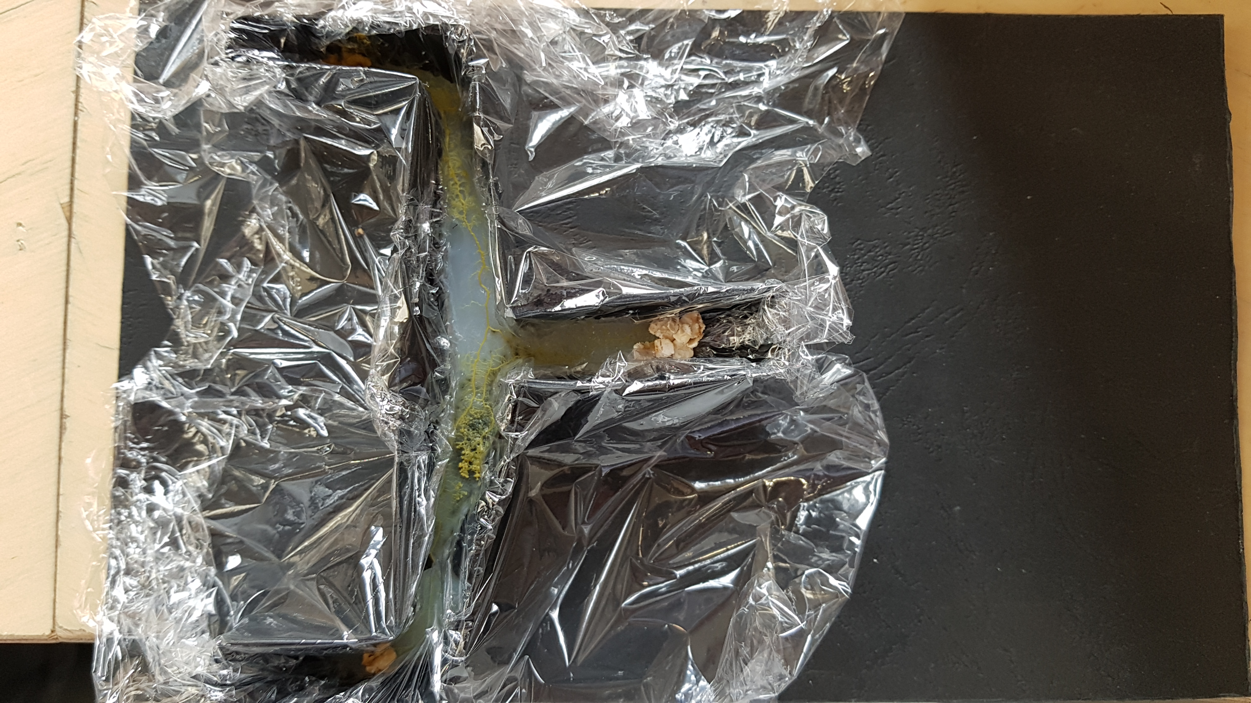
Detailed pictures
Prototype logic circuit (2 gates) test
Very happy with the result of dynamically controlling the Logic Gate, I could once more make the setup more complex. Trying a circuit of 2 serial connected Logic Gates. In this setup the first Logic Gate is in the top part of the Petri dish. Having 2 INPUTS labeled INPUT A1 and INPUT A2 and 1 OUTPUT labelled OUTPUT A. This output is also INPUT B1 for the second Logic Gate, in the centre of the Petri dish with has an second INPUT labelled INPUT B2 and an OUTPUT labelled OUTPUT B, located in the bottom of the Petri dish.
Because I knew I could use the light dynamically, I decide I didn’t have to use the light whilst the Slime Mold was growing. This gave me an opportunity to go with a smaller setup in a Petri dish, enclosed with Cling Film in order to keep foreign organisms out. To be really curtain I whipped the black walls with alcohol to have no foreign agents.
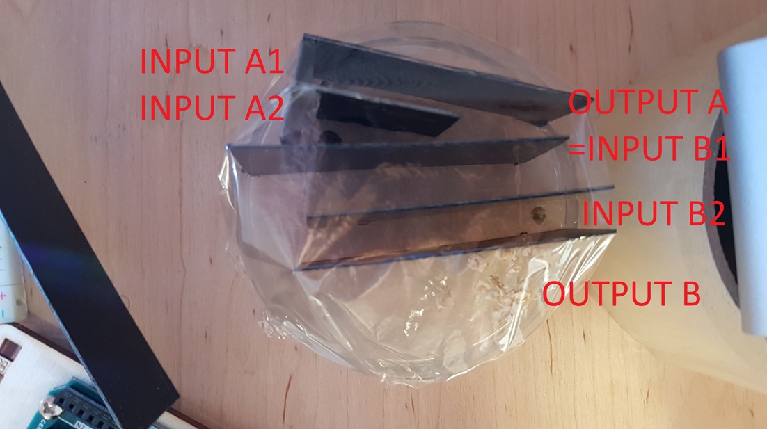
Prototype logic circuit (2 gates) setup
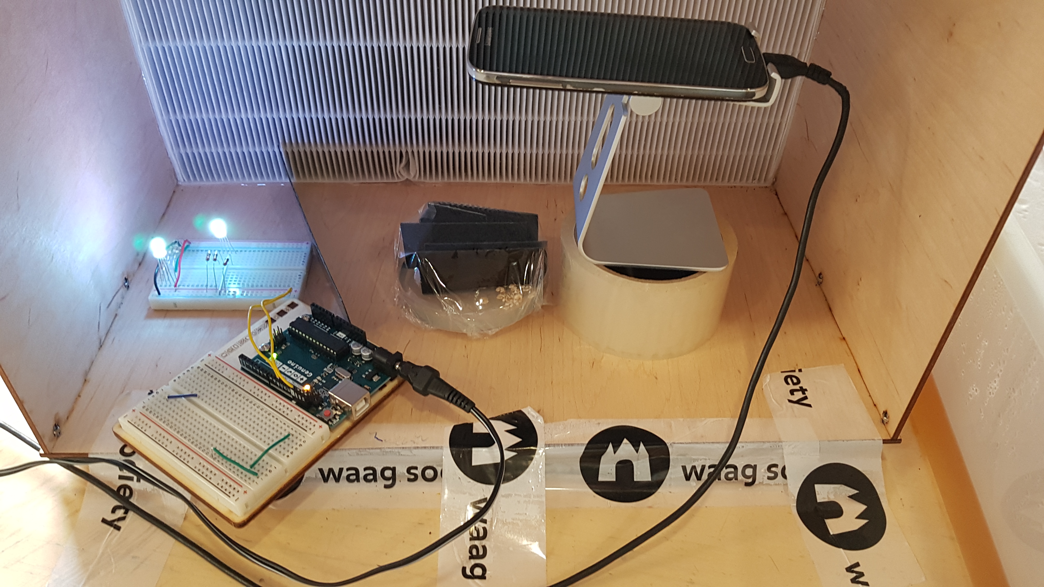
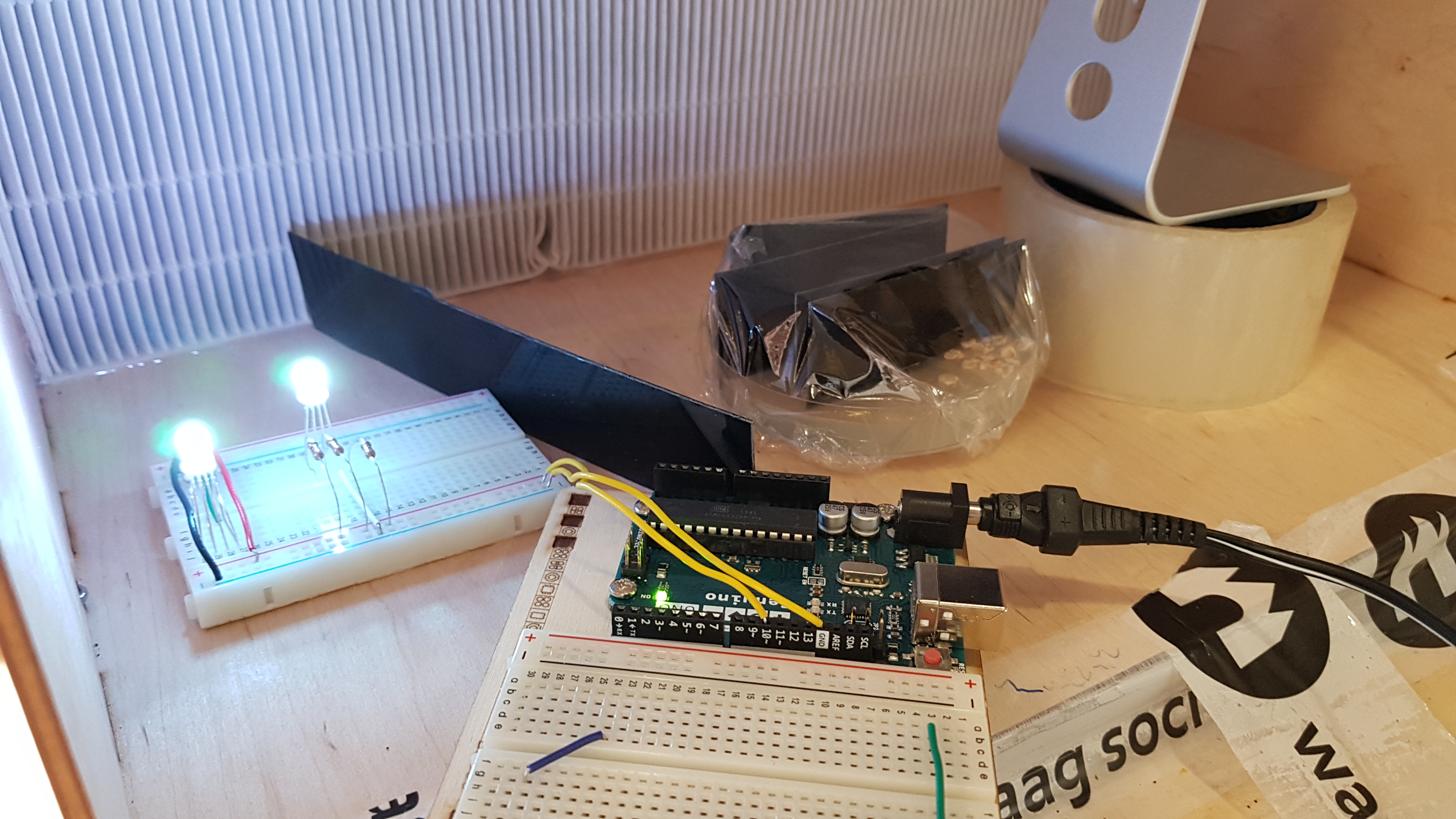
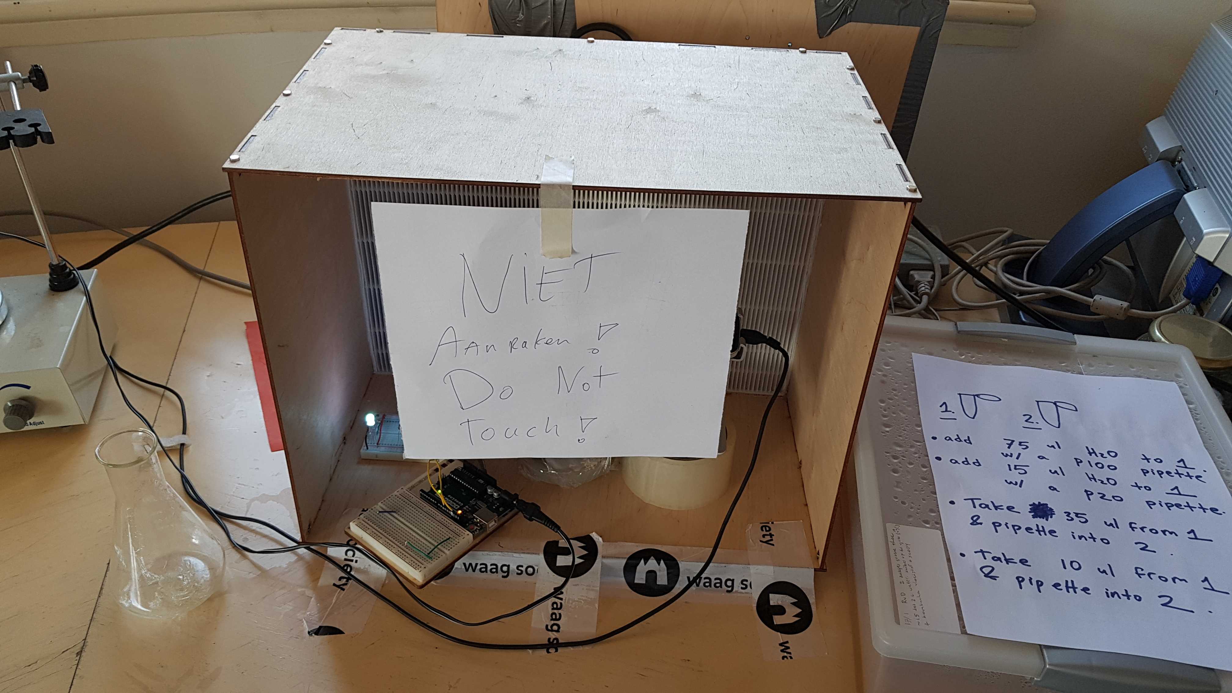
Because nothing was obstructing the view into the Petri dish I had an opportunity to time lapse the growth and behaviour of the Slime Mold. So I used my old Galaxy S4 (Android) and the app (because there is an app for everything!) Framelapse Pro for this. I used the lighting setup to indirectly light the interior of the sterile hood during the night.
Prototype logic circuit (2 gates) result
The result was very disappointing, there was hardly any grow of the 3 Slime molds.
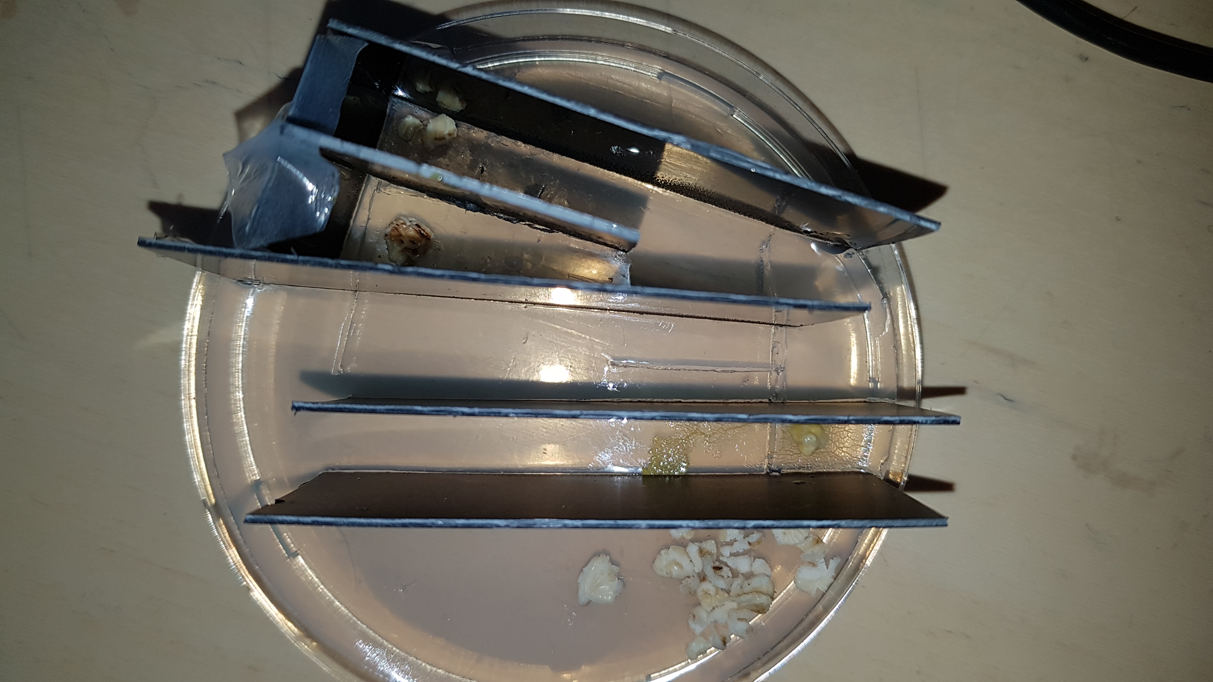
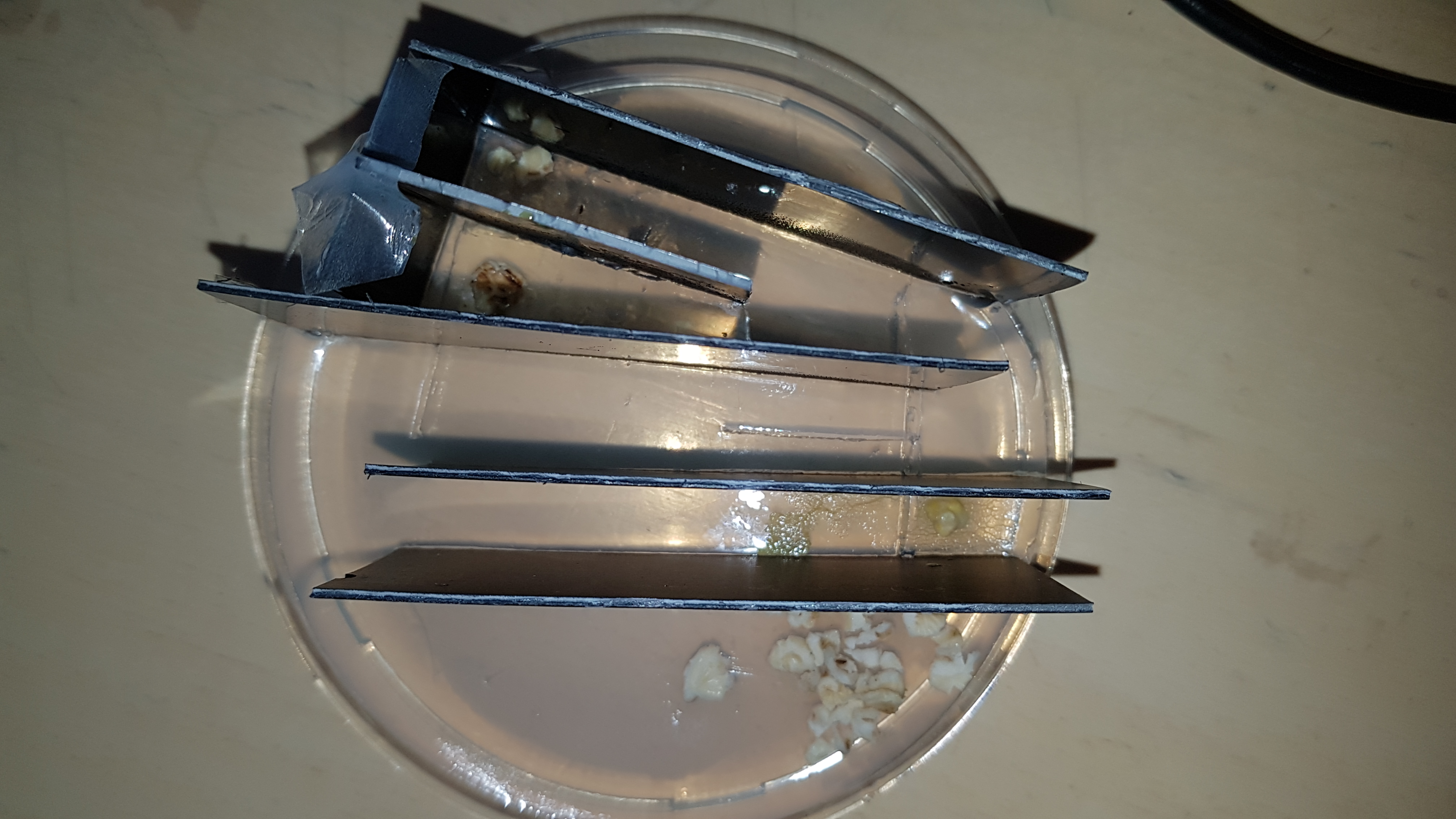
Prototype logic circuit (2 gates) test #2
As with the Light inhibition grow test I repeated this test exactly the same, with one difference this time I didn’t use any alcohol to wipe the black walls clean. Fearing that the alcohol caused the lack of growth the first time. With 1 day to go for the Final Presentation, I made extra sure there was enough Slime Mold on the 3 starting points and laid down 2 instead of 1 oatmeal flakes.
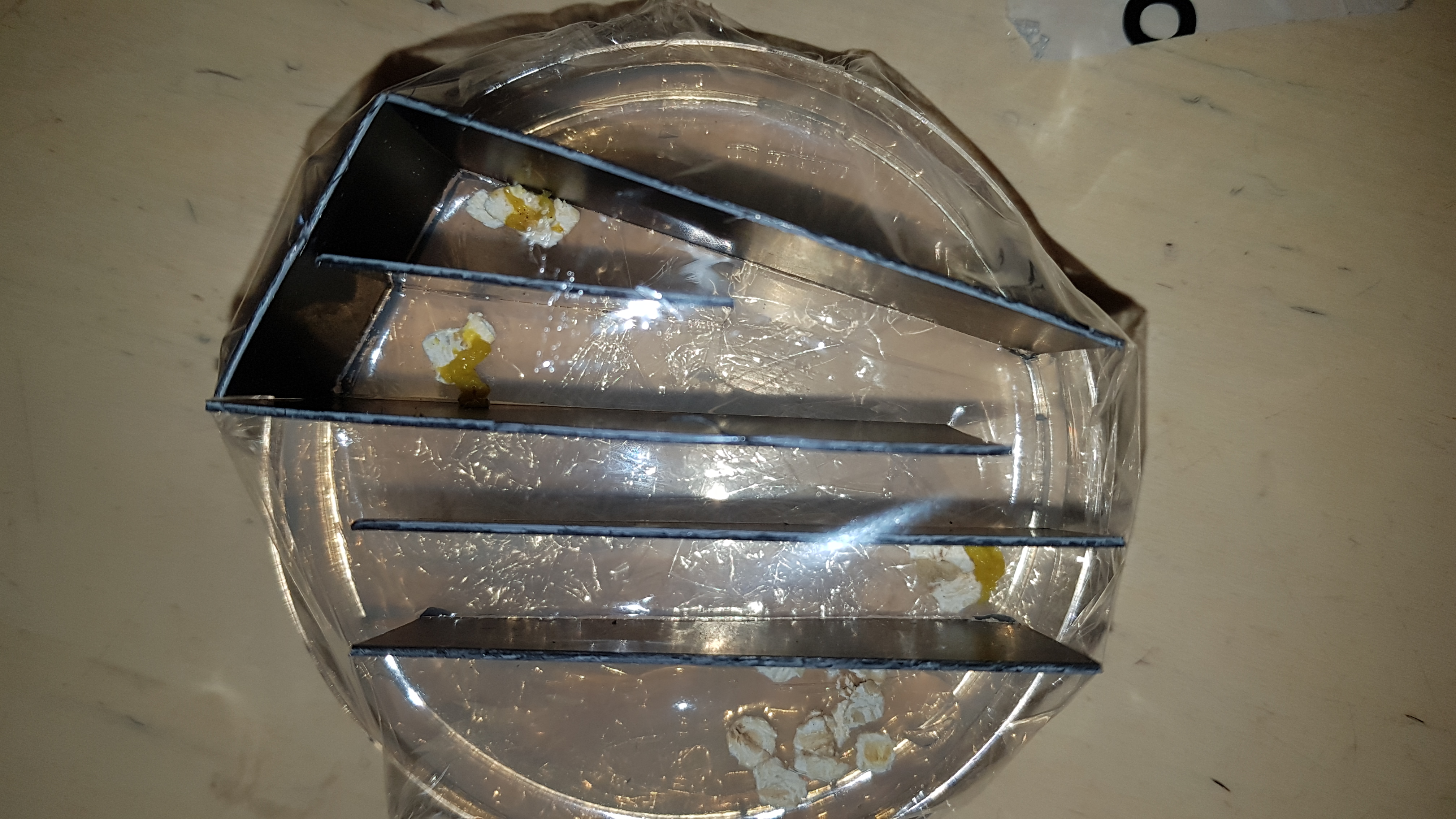
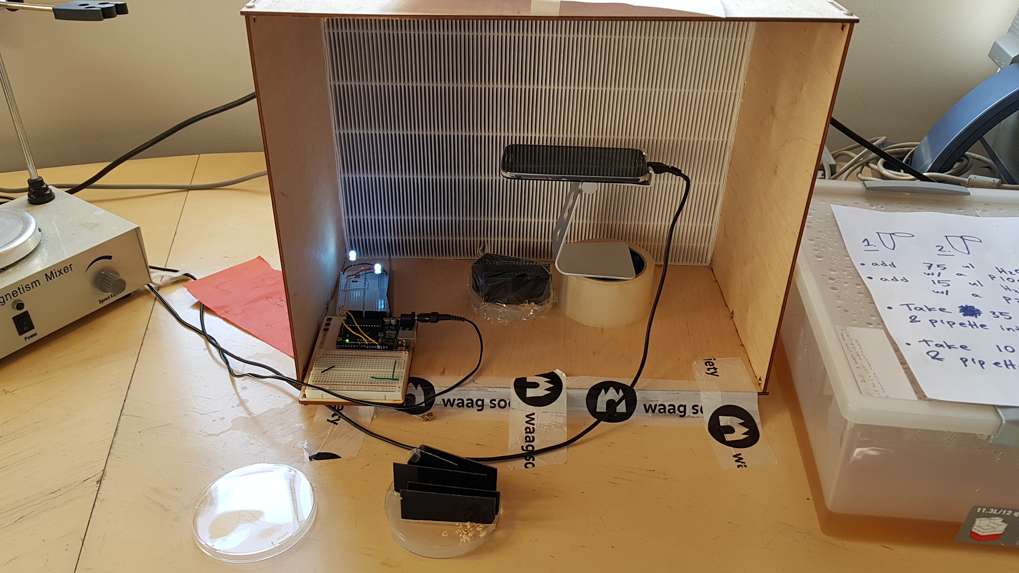
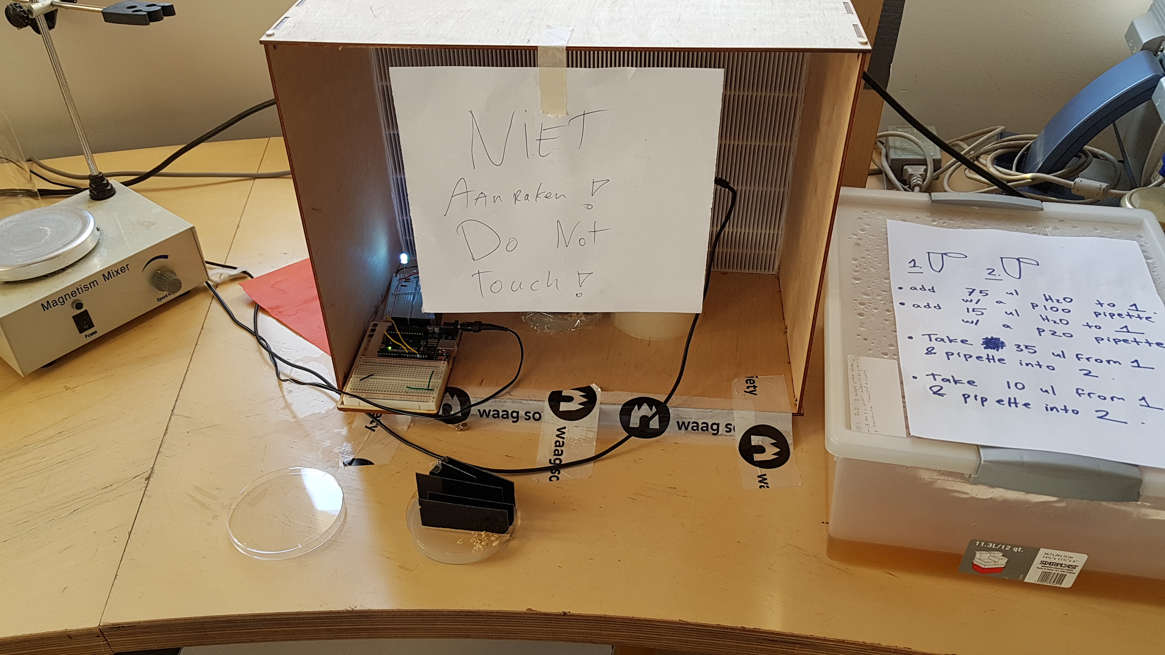
Prototype logic circuit (2 gates) test #2 results
On the last day of the BioHack Academy the results were even more disappointing then the day before.
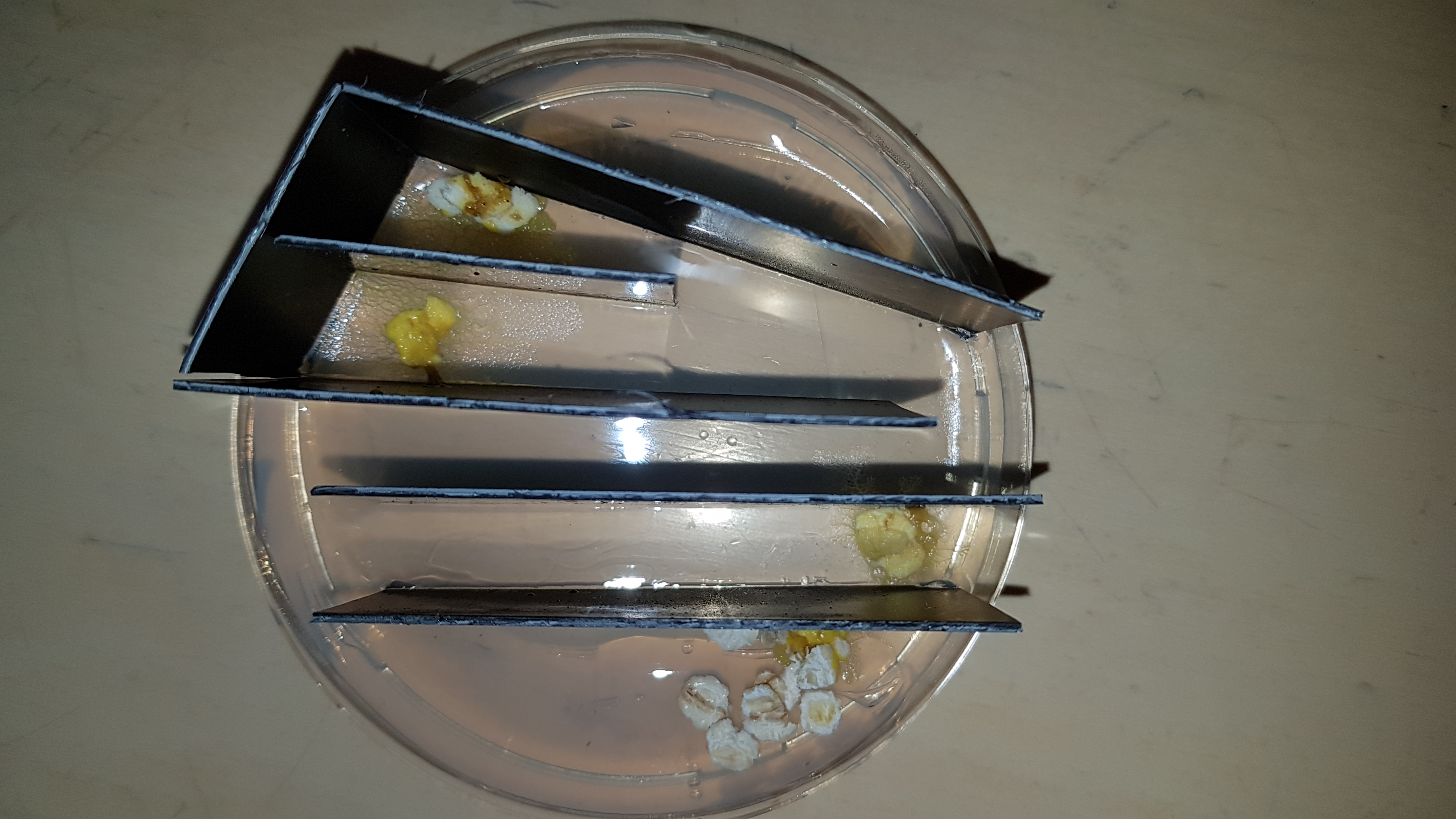
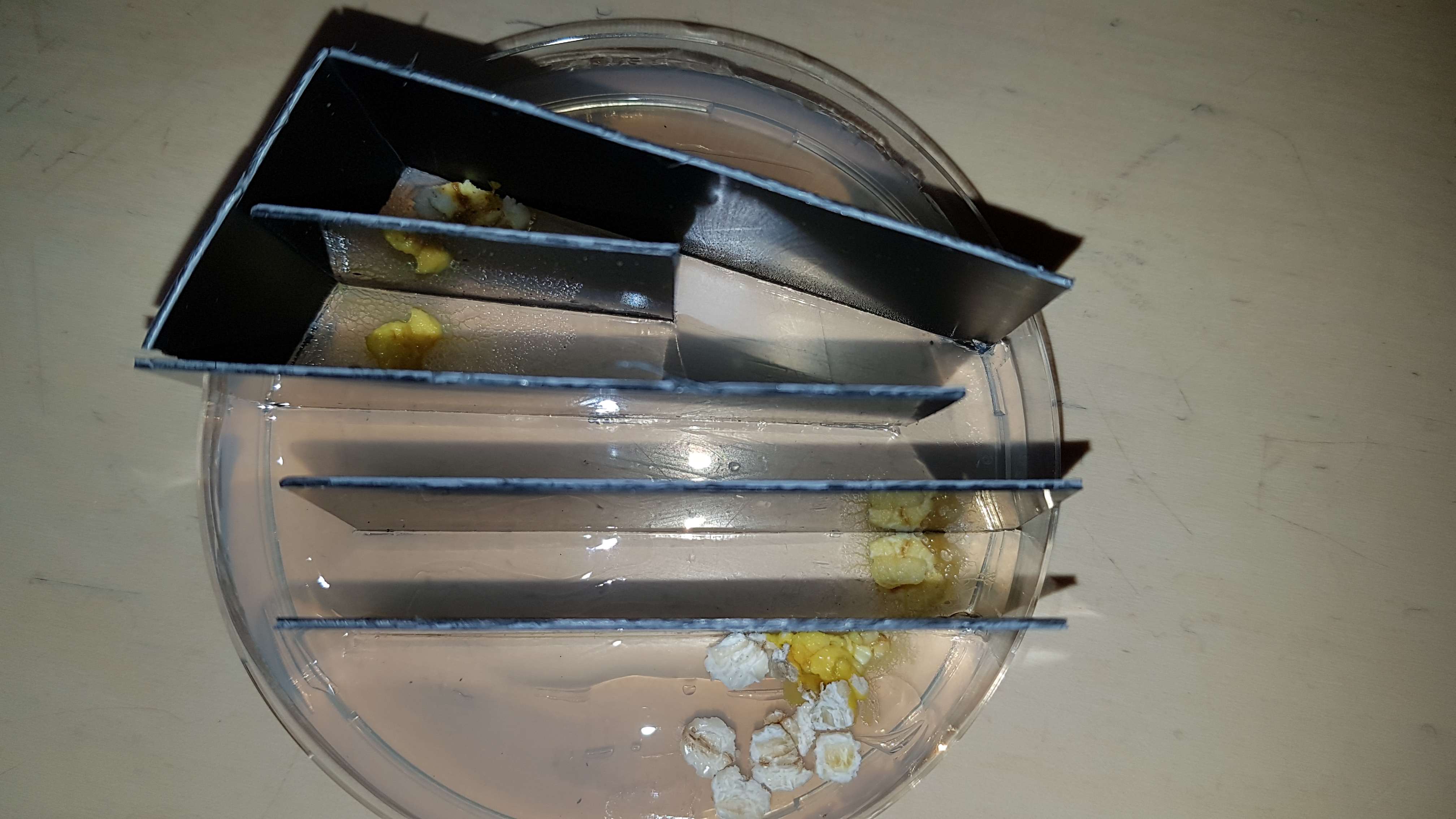
Detailed pictures
Hardly any growth INPUT A1 and A2
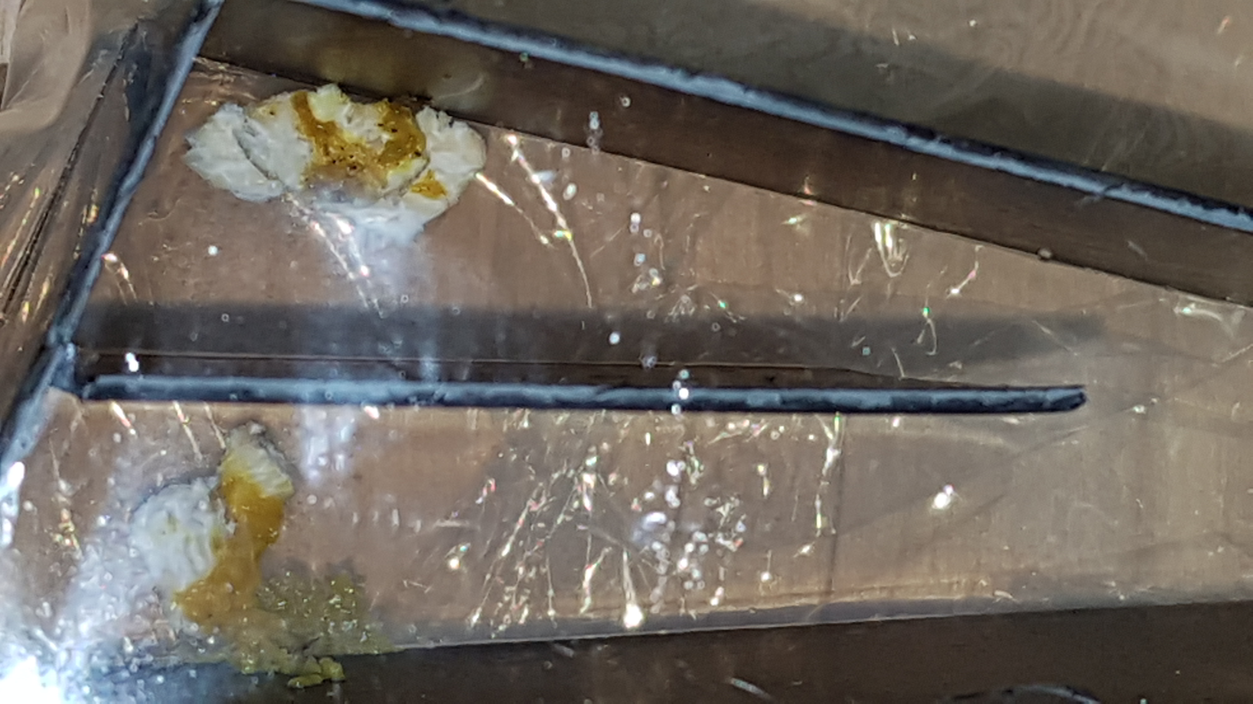
Ironically the most growth came from INPUT B2 who grew underneath a black wall directly to OUTPUT B
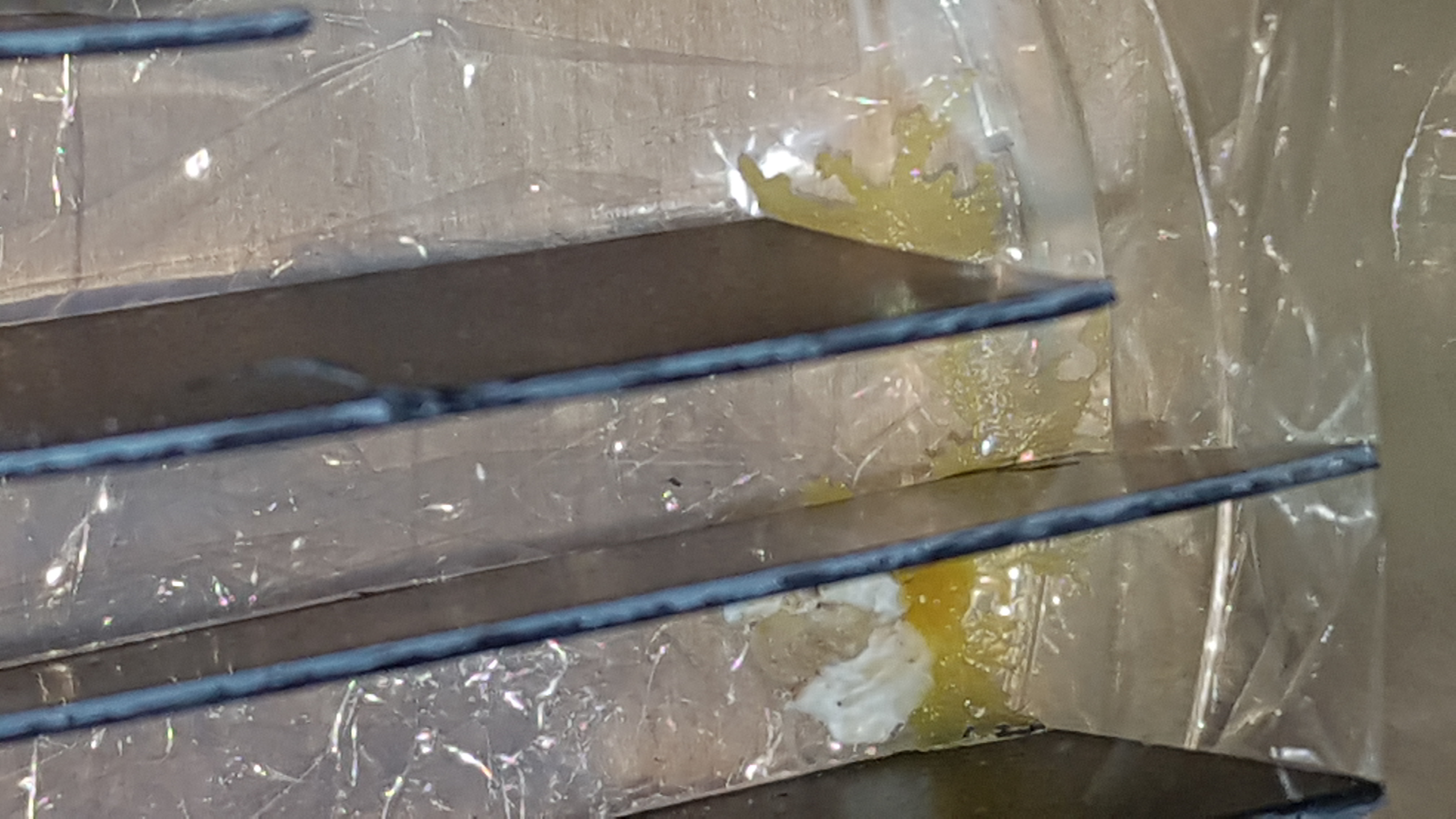
That’s nature!! I had fun AND frustration with it, but mostly I learned a looooooooooooooooooooooooooooooooooooooot!
Cleaning Up
Putting all the Arduino and breadboard stuff back were they belong!
